NAVIGATION SYSTEM, Diagnostic DTC:B15D6

| DTC Code | DTC Name |
|---|---|
| B15D6 | Display Disconnected |
DESCRIPTION
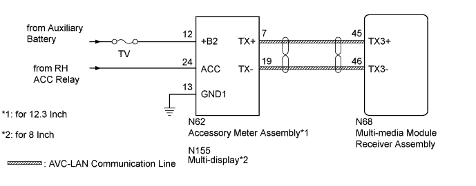
The accessory meter assembly (for 12.3 Inch) or multi-display (for 8 Inch) and multi-media module receiver assembly are connected by an AVC-LAN communication line.
When an AVC-LAN communication error occurs between the multi-media module receiver assembly and accessory meter assembly (for 12.3 Inch) or multi-display (for 8 Inch), this DTC will be stored.
| DTC Code | DTC Detection Condition | Trouble Area |
|---|---|---|
| B15D6* | A device that is listed in the AVC-LAN connected device record of the master unit is missing. |
|
Tech Tips
-
*: Even if no fault is present, this DTC may be stored depending on the auxiliary battery condition or hybrid control system start voltage.
-
The multi-media module receiver assembly is the master unit.
WIRING DIAGRAM
INSPECTION PROCEDURE
Note
Inspect the fuses for circuits related to this system before performing the following inspection procedure.
PROCEDURE
-
CLEAR DTC
-
Clear the DTCs Click here.
NEXT 
-
-
CHECK DTC
-
Recheck for DTCs and check if the same DTC is output again Click here.
OK No DTCs are output
NG 
CHECK HARNESS AND CONNECTOR (ACCESSORY METER ASSEMBLY OR MULTI-DISPLAY - BATTERY AND BODY GROUND) Click here
OK 
USE SIMULATION METHOD TO CHECK Click here
-
-
CHECK HARNESS AND CONNECTOR (ACCESSORY METER ASSEMBLY OR MULTI-DISPLAY - BATTERY AND BODY GROUND)
-
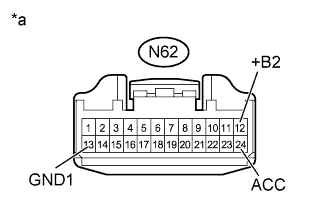
Text in Illustration *a Front view of wire harness connector
(to Accessory Meter Assembly)
for 12.3 Inch
-
Disconnect the accessory meter assembly connector.
-
Measure the resistance according to the value(s) in the table below.
Standard Resistance Tester Connection Condition Specified Condition N62-13 (GND1) - Body ground Always Below 1 Ω -
Measure the voltage according to the value(s) in the table below.
Standard Voltage Tester Connection Condition Specified Condition N62-12 (+B2) - N62-13 (GND1) Always 11 to 14 V N62-24 (ACC) - N62-13 (GND1) Power switch on (ACC) 11 to 14 V
-
-
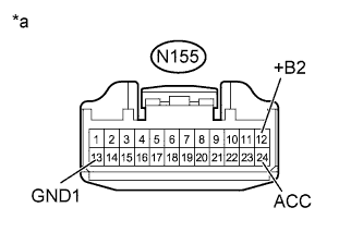
Text in Illustration *a Front view of wire harness connector
(to Multi-display)
for 8 Inch
-
Disconnect the multi-display connector.
-
Measure the resistance according to the value(s) in the table below.
Standard Resistance Tester Connection Condition Specified Condition N155-13 (GND1) - Body ground Always Below 1 Ω -
Measure the voltage according to the value(s) in the table below.
Standard Voltage Tester Connection Condition Specified Condition N155-12 (+B2) - N155-13 (GND1) Always 11 to 14 V N155-24 (ACC) - N155-13 (GND1) Power switch on (ACC) 11 to 14 V
-
NG 
REPAIR OR REPLACE HARNESS OR CONNECTOR
OK
-
-
INSPECT MULTI-MEDIA MODULE RECEIVER ASSEMBLY
-
Remove the multi-media module receiver assembly Click here.
-
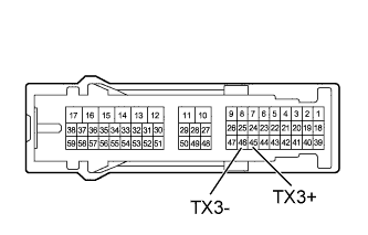
Measure the resistance according to the value(s) in the table below.
Standard Resistance Tester Connection Condition Specified Condition 45 (TX3+) - 46 (TX3-) Always 60 to 80 Ω
NG
REPLACE MULTI-MEDIA MODULE RECEIVER ASSEMBLY Click here
OK
-
-
CHECK HARNESS AND CONNECTOR (MULTI-MEDIA MODULE RECEIVER ASSEMBLY - ACCESSORY METER ASSEMBLY OR MULTI-DISPLAY)
-
for 12.3 Inch
-
Disconnect the N68 multi-media module receiver assembly connector.
-
Disconnect the N62 accessory meter assembly connector.
-
Measure the resistance according to the value(s) in the table below.
Standard Resistance Tester Connection Condition Specified Condition N68-45 (TX3+) - N62-7 (TX+) Always Below 1 Ω N68-46 (TX3-) - N62-19 (TX-) Always Below 1 Ω N68-45 (TX3+) - Body ground Always 10 kΩ or higher N68-46 (TX3-) - Body ground Always 10 kΩ or higher
-
-
for 8 Inch
-
Disconnect the N68 multi-media module receiver assembly connector.
-
Disconnect the N155 multi-display connector.
-
Measure the resistance according to the value(s) in the table below.
Standard Resistance Tester Connection Condition Specified Condition N68-45 (TX3+) - N155-7 (TX+) Always Below 1 Ω N68-46 (TX3-) - N155-19 (TX-) Always Below 1 Ω N68-45 (TX3+) - Body ground Always 10 kΩ or higher N68-46 (TX3-) - Body ground Always 10 kΩ or higher
-
NG
REPAIR OR REPLACE HARNESS OR CONNECTOR
OK
-
-
REPLACE ACCESSORY METER ASSEMBLY OR MULTI-DISPLAY
-
for 12.3 Inch
-
Replace the accessory meter assembly with a new or normally functioning one Click here.
-
-
for 8 Inch
-
Replace the multi-display with a new or normally functioning one Click here.
-
NEXT
-
-
CLEAR DTC
-
Clear the DTCs Click here.
NEXT
-
-
CHECK DTC
-
Recheck for DTCs and check if the same DTC is output again Click here.
OK No DTCs are output
NG
REPLACE MULTI-MEDIA MODULE RECEIVER ASSEMBLY Click here
OK
END (ACCESSORY METER ASSEMBLY OR MULTI-DISPLAY IS DEFECTIVE)
-