AUDIO AND VISUAL SYSTEM Pointer Displayed/not Displayed Repeatedly
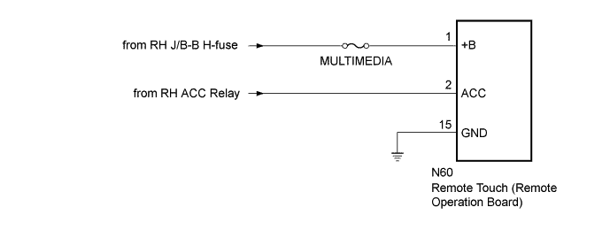
WIRING DIAGRAM
INSPECTION PROCEDURE
Note
Inspect the fuses for circuits related to this system before performing the following inspection procedure.
PROCEDURE
-
CONFIRM SYMPTOMS
-
Recheck the situation when the malfunction occurs.
Tech Tips
-
When a user lays their hand on the remote touch switch knob, the pointer may be displayed and hidden repeatedly according to the knob movement.
-
When driving on a rough road where the vehicle lurches or shakes around due to the bumps, the remote touch switch knob may move unexpectedly as a result.
Result Result Proceed to Symptom occurs in any situation. A Symptom occurs when hand is rested on the remote touch switch knob while driving. B Symptom occurs when driving on a rough road that causes the vehicle to lurch or shake around. C -
B 
END
C 
CHECK CONNECTOR CONNECTION CONDITION Click here
A 
-
-
CHECK FOR FOREIGN MATTER
-
Check if there is any foreign matter around the remote touch screen that interferes with operation of the screen.
OK There is no foreign matter around the remote touch screen that interferes with operation of the screen.
NG
FOREIGN MATTER (CHECK OPERATION AGAIN)
OK 
USE SIMULATION METHOD TO CHECK Click here
-
-
CHECK CONNECTOR CONNECTION CONDITION
-
Check if the remote operation controller assembly connector is securely connected.
OK The connector is securely connected.
NG
SECURELY CONNECTED
OK
-
-
CHECK HARNESS AND CONNECTOR (REMOTE TOUCH [REMOTE OPERATION BOARD] - BATTERY AND BODY GROUND)
-
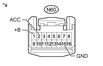
Text in Illustration *a Front view of wire harness connector
(to Remote Touch [Remote Operation Board])
Disconnect the remote touch (remote operation board) connector.
-
Measure the voltage according to the value(s) in the table below.
Standard Voltage Tester Connection Switch Condition Specified Condition N60-1 (+B) - Body ground Power switch off 11 to 14 V N60-2 (ACC) - Body ground Power switch on (ACC) 11 to 14 V -
Measure the resistance according to the value(s) in the table below.
Standard Resistance Tester Connection Condition Specified Condition N60-15 (GND) - Body ground Always Below 1 Ω
NG
REPAIR OR REPLACE HARNESS OR CONNECTOR
OK
REPLACE REMOTE TOUCH (REMOTE OPERATION BOARD) Click here
-