AUDIO AND VISUAL SYSTEM Visual Mute Signal Circuit between Radio Receiver and Multi-display
DESCRIPTION
-
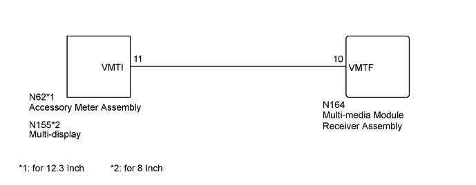
*1: for 12.3 Inch
-
*2: for 8 Inch
The multi-media module receiver assembly sends a visual mute signal to the accessory meter assembly*1 or multi-display*2. As a result, a black screen is inserted when the screen changes so that noise and distorted images are not displayed.
When an open exists in the circuit, noise and distorted images will be displayed instead of a black screen.
When a short exists in the circuit, even though the accessory meter assembly*1 or multi-display*2 is operating normally, noise and distorted images will be displayed (black screen will not be displayed) during screen changes or the black screen will always be displayed.
WIRING DIAGRAM
INSPECTION PROCEDURE
PROCEDURE
-
CHECK MULTI-MEDIA MODULE RECEIVER ASSEMBLY
-
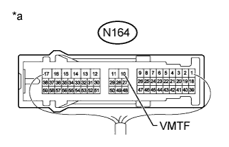
Text in Illustration *a Component with harness connected
(Multi-media Module Receiver Assembly)
Measure the voltage according to the value(s) in the table below.
Standard Voltage Tester Connection Condition Specified Condition N164-10 (VMTF) - Body ground Power switch on (ACC), screen display changes. 3.5 V or higher → Below 1 V → 3.5 V or higher
NG 
REPLACE MULTI-MEDIA MODULE RECEIVER ASSEMBLY Click here
OK 
-
-
CHECK HARNESS AND CONNECTOR (MULTI-MEDIA MODULE RECEIVER ASSEMBLY - ACCESSORY METER ASSEMBLY OR MULTI-DISPLAY)
-
*1: for 12.3 Inch
-
*2: for 8 Inch
-
Disconnect the N164 multi-media module receiver assembly connector.
-
Disconnect the N62*1 accessory meter assembly connector.
-
Disconnect the N155*2 multi-display connector.
-
Measure the resistance according to the value(s) in the table below.
Standard Resistance for 12.3 Inch Tester Connection Condition Specified Condition N164-10 (VMTF) - N62-11 (VMTI) Always Below 1 Ω N164-10 (VMTF) - Body ground Always 10 kΩ or higher for 8 Inch Tester Connection Condition Specified Condition N164-10 (VMTF) - N155-11 (VMTI) Always Below 1 Ω N164-10 (VMTF) - Body ground Always 10 kΩ or higher
NG
REPAIR OR REPLACE HARNESS OR CONNECTOR
OK 
PROCEED TO NEXT SUSPECTED AREA SHOWN IN PROBLEM SYMPTOMS TABLE Click here
-