AUDIO AND VISUAL SYSTEM, Diagnostic DTC:B1579

| DTC Code | DTC Name |
|---|---|
| B1579 | Voice Recognition Microphone Disconnected |
DESCRIPTION
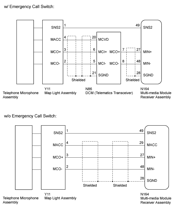
The multi-media module receiver assembly and map light assembly (telephone microphone assembly) are connected to each other using the microphone connection detection signal lines.
This DTC is stored when a microphone connection detection signal line is disconnected.
| DTC Code | DTC Detection Condition | Trouble Area |
|---|---|---|
| B1579 | Telephone microphone signal is lost. |
|
-
*: w/ Emergency Call Switch
WIRING DIAGRAM
INSPECTION PROCEDURE
PROCEDURE
-
CONFIRM MODEL
-
Choose the model to be inspected.
Result Result Proceed to w/o Emergency Call Switch A w/ Emergency Call Switch B
B 
CHECK HARNESS OR CONNECTOR (MULTI-MEDIA MODULE RECEIVER ASSEMBLY - MAP LIGHT ASSEMBLY) Click here
A 
-
-
CHECK HARNESS AND CONNECTOR (MULTI-MEDIA MODULE RECEIVER ASSEMBLY - MAP LIGHT ASSEMBLY)
-
Disconnect the N164 multi-media module receiver assembly connector.
-
Disconnect the Y11 map light assembly connector.
-
Measure the resistance according to the value(s) in the table below.
Standard Resistance Tester Connection Condition Specified Condition N164-49 (SNS2) - Y11-1 (SNS2) Always Below 1 Ω N164-29 (MACC) - Y11-4 (MACC) Always Below 1 Ω N164-27 (MIN+) - Y11-3 (MCO+) Always Below 1 Ω N164-48 (MIN-) - Y11-2 (MCO-) Always Below 1 Ω N164-49 (SNS2) - Body ground Always 10 kΩ or higher N164-29 (MACC) - Body ground Always 10 kΩ or higher N164-27 (MIN+) - Body ground Always 10 kΩ or higher N164-48 (MIN-) - Body ground Always 10 kΩ or higher N164-28 (SGND) - Body ground Always 10 kΩ or higher
NG 
REPAIR OR REPLACE HARNESS OR CONNECTOR
OK
-
-
CHECK MULTI-MEDIA MODULE RECEIVER ASSEMBLY
-
Reconnect the multi-media module receiver assembly connector.
-
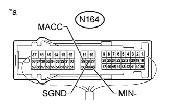
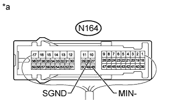
Text in Illustration *a Component with harness connected
(Multi-media Module Receiver Assembly)
Measure the resistance according to the value(s) in the table below.
Standard Resistance Tester Connection Condition Specified Condition N164-28 (SGND) - Body ground Always Below 1 Ω N164-48 (MIN-) - Body ground Always Below 1 Ω -
Measure the voltage according to the value(s) in the table below.
Standard Voltage Tester Connection Switch Condition Specified Condition N164-29 (MACC) - Body ground Power switch on (ACC) 4 to 6 V
NG
REPLACE MULTI-MEDIA MODULE RECEIVER ASSEMBLY Click here
OK
-
-
INSPECT MAP LIGHT ASSEMBLY
-
Remove the map light assembly Click here.
-
Measure the resistance according to the value(s) in the table below.
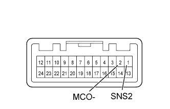
Standard Resistance Tester Connection Condition Specified Condition 2 (MCO-) - 1 (SNS2) Always Below 1 Ω
NG
CHECK TELEPHONE MICROPHONE ASSEMBLY Click here
OK
-
-
CHECK MAP LIGHT ASSEMBLY
-
Reconnect the multi-media module receiver assembly connector.
-
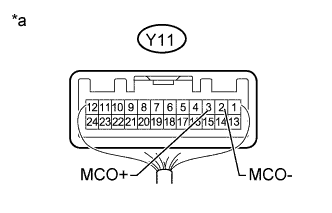
Text in Illustration *a Component with harness connected
(Map Light Assembly)
Reconnect the map light assembly connector.
-
Turn the power switch on (ACC).
-
Connect an oscilloscope to terminals Y11-3 (MCO+) and Y11-2 (MCO-) of the map light assembly connector.
-
Check the waveform of the telephone microphone assembly using the oscilloscope.
Result Result Proceed to A waveform synchronized with the voice input to the map light assembly is not output. A A waveform synchronized with the voice input to the map light assembly is output. B
B
REPLACE MULTI-MEDIA MODULE RECEIVER ASSEMBLY Click here
A
-
-
CHECK TELEPHONE MICROPHONE ASSEMBLY
-
Replace the telephone microphone assembly with a new or normally functioning one Click here.
-
Check if the same DTC is output again.
Result Result Proceed to No DTCs are output. A DTCs are output. B
B
REPLACE MAP LIGHT ASSEMBLY Click here
A 
END (TELEPHONE MICROPHONE ASSEMBLY IS DEFECTIVE)
-
-
CHECK HARNESS OR CONNECTOR (MULTI-MEDIA MODULE RECEIVER ASSEMBLY - MAP LIGHT ASSEMBLY)
-
Disconnect the N164 multi-media module receiver assembly connector.
-
Disconnect the Y11 map light assembly connector.
-
Measure the resistance according to the value(s) in the table below.
Standard Resistance Tester Connection Condition Specified Condition N164-49 (SNS2) - Y11-1 (SNS2) Always Below 1 Ω
NG
REPAIR OR REPLACE HARNESS OR CONNECTOR
OK
-
-
CHECK HARNESS OR CONNECTOR (MULTI-MEDIA MODULE RECEIVER ASSEMBLY - DCM [TELEMATICS TRANSCEIVER])
-
Disconnect the N164 multi-media module receiver assembly connector.
-
Disconnect the N86 DCM (telematics transceiver) connector.
-
Measure the resistance according to the value(s) in the table below.
Standard Resistance Tester Connection Condition Specified Condition N164-27 (MIN+) - N86-7 (MCO+) Always Below 1 Ω N164-48 (MIN-) - N86-8 (MCO-) Always Below 1 Ω N164-27 (MIN+) - Body ground Always 10 kΩ or higher N164-48 (MIN-) - Body ground Always 10 kΩ or higher N164-28 (SGND) - Body ground Always 10 kΩ or higher
NG
REPAIR OR REPLACE HARNESS OR CONNECTOR
OK
-
-
CHECK HARNESS OR CONNECTOR (DCM [TELEMATICS TRANSCEIVER] - MAP LIGHT ASSEMBLY)
-
Disconnect the N86 DCM (telematics transceiver) connector.
-
Disconnect the Y11 map light assembly connector.
-
Measure the resistance according to the value(s) in the table below.
Standard Resistance Tester Connection Condition Specified Condition N86-20 (MCVD) - Y11-4 (MACC) Always Below 1 Ω N86-6 (MCI+) - Y11-3 (MCO+) Always Below 1 Ω N86-5 (MCI-) - Y11-2 (MCO-) Always Below 1 Ω N86-20 (MCVD) - Body ground Always 10 kΩ or higher N86-6 (MCI+) - Body ground Always 10 kΩ or higher N86-5 (MCI-) - Body ground Always 10 kΩ or higher N86-21 (SGND) - Body ground Always 10 kΩ or higher
NG
REPAIR OR REPLACE HARNESS OR CONNECTOR
OK
-
-
CHECK MULTI-MEDIA MODULE RECEIVER ASSEMBLY
-
Text in Illustration *a Component with harness connected
(Multi-media Module Receiver Assembly)
Reconnect the multi-media module receiver assembly connector.
-
Measure the resistance according to the value(s) in the table below.
Standard Resistance Tester Connection Condition Specified Condition N164-28 (SGND) - Body ground Always Below 1 Ω N164-48 (MIN-) - Body ground Always Below 1 Ω
NG
REPLACE MULTI-MEDIA MODULE RECEIVER ASSEMBLY Click here
OK
-
-
CHECK DCM (TELEMATICS TRANSCEIVER)
-
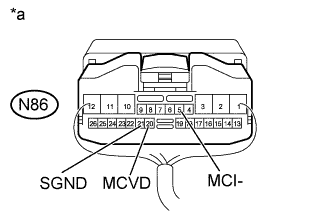
Text in Illustration *a Component with harness connected
(DCM [Telematics Transceiver])
Reconnect the DCM (telematics transceiver) connector.
-
Measure the resistance according to the value(s) in the table below.
Standard Resistance Tester Connection Condition Specified Condition N86-21 (SGND) - Body ground Always Below 1 Ω N86-5 (MCI-) - Body ground Always Below 1 Ω -
Measure the voltage according to the value(s) in the table below.
Standard Voltage Tester Connection Switch Condition Specified Condition N86-20 (MCVD) - Body ground Power switch on (ACC) 4 to 6 V
NG
REPLACE DCM (TELEMATICS TRANSCEIVER) Click here
OK
-
-
INSPECT MAP LIGHT ASSEMBLY
-
Remove the map light assembly Click here.
-
Measure the resistance according to the value(s) in the table below.
Standard Resistance Tester Connection Condition Specified Condition 2 (MCO-) - 1 (SNS2) Always Below 1 Ω
NG
CHECK TELEPHONE MICROPHONE ASSEMBLY Click here
OK
-
-
CHECK MAP LIGHT ASSEMBLY
-
Reconnect the multi-media module receiver assembly connector.
-
Reconnect the DCM (telematics transceiver) connector.
-
Text in Illustration *a Component with harness connected
(Map Light Assembly)
Reconnect the map light assembly connector.
-
Turn the power switch on (ACC).
-
Connect an oscilloscope to terminals Y11-3 (MCO+) and Y11-2 (MCO-) of the map light assembly connector.
-
Check the waveform of the telephone microphone assembly using the oscilloscope.
Result Result Proceed to A waveform synchronized with the voice input to the map light assembly is not output. A A waveform synchronized with the voice input to the map light assembly is output. B
B
REPLACE MULTI-MEDIA MODULE RECEIVER ASSEMBLY Click here
A
-
-
CHECK TELEPHONE MICROPHONE ASSEMBLY
-
Replace the telephone microphone assembly with a new or normally functioning one Click here.
-
Check if the same DTC is output again.
Result Result Proceed to No DTCs are output. A DTCs are output. B
B
REPLACE MAP LIGHT ASSEMBLY Click here
A
END (TELEPHONE MICROPHONE ASSEMBLY IS DEFECTIVE)
-