AUDIO AND VISUAL SYSTEM, Diagnostic DTC:B1321

| DTC Code | DTC Name |
|---|---|
| B1321 | Lost Communication with EMV |
DESCRIPTION
The multi-media module receiver assembly stores this DTC when it cannot receive data from a device that is stored in memory as being connected to the multi-media module receiver assembly.
| DTC Code | DTC Detection Condition | Trouble Area |
|---|---|---|
| B1321 | The multi-media module receiver assembly cannot receive data from a device that is stored in memory as being connected to the multi-media module receiver assembly. |
|
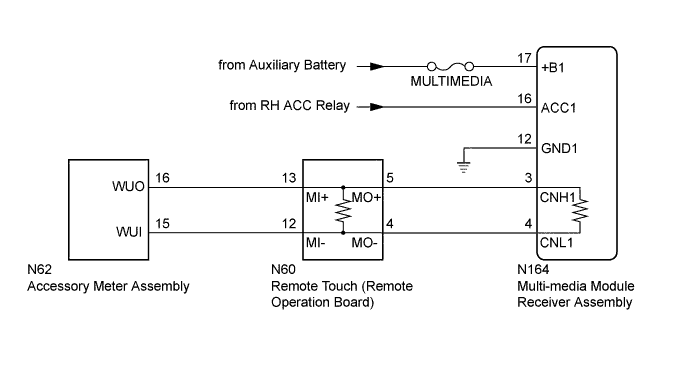
WIRING DIAGRAM
INSPECTION PROCEDURE
Note
-
Before measuring the resistance of the CAN bus, turn the power switch off and leave the vehicle for 1 minute or more without operating the key, switches or opening or closing the doors. After that, disconnect the cable from the negative (-) auxiliary battery terminal and leave the vehicle for 1 minute or more before measuring the resistance.
-
After turning the power switch off, waiting time may be required before disconnecting the cable from the auxiliary battery terminal. Therefore, make sure to read the disconnecting the cable from the auxiliary battery terminal notice before proceeding with work Click here.
-
Inspect the fuses for circuits related to this system before performing the following inspection procedure.
Tech Tips
-
Operating the power switch, any switches or any doors triggers related ECU and sensor communication with the CAN, which causes resistance variation.
-
Even after DTCs are cleared, if a DTC is stored again after driving the vehicle for a while, the malfunction may be occurring due to vibration of the vehicle. In such a case, wiggling the ECUs or wire harness while performing the inspection below may help determine the cause of the malfunction.
PROCEDURE
-
CHECK CAN BUS WIRE (CHECK MAIN WIRE FOR DISCONNECTION, CHECK BUS LINE FOR SHORT CIRCUIT)
-
Text in Illustration *a Component with harness connected
(Multi-media Module Receiver Assembly)
Disconnect the cable from the negative (-) auxiliary battery terminal before measuring the resistances of the CAN main wire and the CAN branch wire.
-
Measure the resistance according to the value(s) in the table below.
Standard Resistance Tester Connection Condition Specified Condition Resistance: Malfunction N164-3 (CNH1) - N164-4 (CNL1) Cable disconnected from negative (-) auxiliary battery terminal 54 to 69 Ω Below 53 Ω: Short in line N164-3 (CNH1) - N164-4 (CNL1) Cable disconnected from negative (-) auxiliary battery terminal 54 to 69 Ω Higher than 70 Ω: Open in CAN main bus line N164-3 (CNH1) - N164-17 (+B1) Cable disconnected from negative (-) auxiliary battery terminal 6 kΩ or higher Below 6 kΩ: +B short N164-4 (CNL1) - N164-17 (+B1) Cable disconnected from negative (-) auxiliary battery terminal 6 kΩ or higher Below 6 kΩ: +B short N164-3 (CNH1) - N164-12 (GND1) Cable disconnected from negative (-) auxiliary battery terminal 200 Ω or higher Below 200 Ω: Ground short N164-4 (CNL1) - N164-12 (GND1) Cable disconnected from negative (-) auxiliary battery terminal 200 Ω or higher Below 200 Ω: Ground short Result Result Proceed to OK A NG
-
Open in CAN main bus line
B NG
-
Short in line
-
+B short
-
GND short
C -
B 
CHECK FOR OPEN IN CAN BUS WIRE (MULTI-MEDIA MODULE RECEIVER ASSEMBLY - REMOTE TOUCH) Click here
C
CHECK FOR SHORT IN CAN BUS WIRE (REMOTE TOUCH - MULTI-MEDIA MODULE RECEIVER ASSEMBLY) Click here
A 
-
-
CHECK HARNESS AND CONNECTOR (MULTI-MEDIA MODULE RECEIVER ASSEMBLY - BATTERY AND BODY GROUND)
-
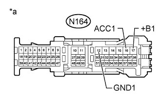
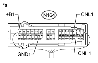
Text in Illustration *a Front view of wire harness connector
(to Multi-media Module Receiver Assembly)
Connect the cable to the negative (-) auxiliary battery terminal.
-
Disconnect the multi-media module receiver assembly connector.
-
Measure the voltage according to the value(s) in the table below.
Standard Voltage Tester Connection Switch Condition Specified Condition N164-16 (ACC1) - Body ground Power switch on (ACC) 11 to 14 V N164-17 (+B1) - Body ground Power switch off 11 to 14 V -
Measure the resistance according to the value(s) in the table below.
Standard Resistance Tester Connection Condition Specified Condition N164-12 (GND1) - Body ground Always Below 1 Ω
NG 
REPAIR OR REPLACE HARNESS OR CONNECTOR
OK 
REPLACE MULTI-MEDIA MODULE RECEIVER ASSEMBLY Click here
-
-
CHECK FOR OPEN IN CAN BUS WIRE (MULTI-MEDIA MODULE RECEIVER ASSEMBLY - REMOTE TOUCH)
-
Text in Illustration *a Front view of wire harness connector
(to Multi-media Module Receiver Assembly)
Disconnect the multi-media module receiver assembly connector.
-
Measure the resistance according to the value(s) in the table below.
Standard Resistance Tester Connection Condition Specified Condition N164-3 (CNH1) - N164-4 (CNL1) Cable disconnected from negative (-) auxiliary battery terminal 108 to 132 Ω
NG
CHECK FOR OPEN IN CAN BUS WIRE (REMOTE TOUCH - MULTI-MEDIA MODULE RECEIVER ASSEMBLY) Click here
OK
REPLACE MULTI-MEDIA MODULE RECEIVER ASSEMBLY Click here
-
-
CHECK FOR OPEN IN CAN BUS WIRE (REMOTE TOUCH - MULTI-MEDIA MODULE RECEIVER ASSEMBLY)
-
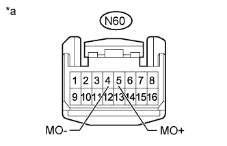
Text in Illustration *a Front view of wire harness connector
(to Remote Touch [Remote Operation Board])
Disconnect the remote touch (remote operation board) connector.
-
Measure the resistance according to the value(s) in the table below.
Standard Resistance Tester Connection Condition Specified Condition N60-5 (MO+) - N60-4 (MO-) Cable disconnected from negative (-) auxiliary battery terminal 108 to 132 Ω
NG
REPAIR OR REPLACE CAN MAIN WIRE OR CONNECTOR (REMOTE TOUCH - MULTI-MEDIA MODULE RECEIVER ASSEMBLY)
OK
REPLACE REMOTE TOUCH (REMOTE OPERATION BOARD) Click here
-
-
CHECK FOR SHORT IN CAN BUS WIRE (REMOTE TOUCH - MULTI-MEDIA MODULE RECEIVER ASSEMBLY)
-
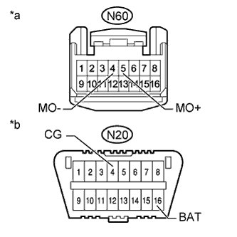
Text in Illustration *a Front view of wire harness connector
(to Remote Touch [Remote Operation Board])
*b Front view of DLC3 Disconnect the remote touch (remote operation board) connector.
-
Measure the resistance according to the value(s) in the table below.
Standard Resistance Tester Connection Condition Specified Condition N60-4 (MO-) - N60-5 (MO+) Cable disconnected from negative (-) auxiliary battery terminal 108 to 132 Ω N60-4 (MO-) - N20-16 (BAT) Cable disconnected from negative (-) auxiliary battery terminal 6 kΩ or higher N60-5 (MO+) - N20-16 (BAT) Cable disconnected from negative (-) auxiliary battery terminal 6 kΩ or higher N60-4 (MO-) - N20-4 (CG) Cable disconnected from negative (-) auxiliary battery terminal 200 Ω or higher N60-5 (MO+) - N20-4 (CG) Cable disconnected from negative (-) auxiliary battery terminal 200 Ω or higher
NG
CHECK FOR SHORT IN CAN BUS WIRE (MULTI-MEDIA MODULE RECEIVER ASSEMBLY) Click here
OK
-
-
CHECK FOR SHORT IN CAN BUS WIRE (REMOTE TOUCH - ACCESSORY METER ASSEMBLY)
-
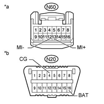
Text in Illustration *a Front view of wire harness connector
(to Remote Touch [Remote Operation Board])
*b Front view of DLC3 Disconnect the remote touch (remote operation board) connector.
-
Measure the resistance according to the value(s) in the table below.
Standard Resistance Tester Connection Condition Specified Condition N60-12 (MI-) - N60-13 (MI+) Cable disconnected from negative (-) auxiliary battery terminal 200 Ω or higher N60-12 (MI-) - N20-16 (BAT) Cable disconnected from negative (-) auxiliary battery terminal 6 kΩ or higher N60-13 (MI+) - N20-16 (BAT) Cable disconnected from negative (-) auxiliary battery terminal 6 kΩ or higher N60-12 (MI-) - N20-4 (CG) Cable disconnected from negative (-) auxiliary battery terminal 200 Ω or higher N60-13 (MI+) - N20-4 (CG) Cable disconnected from negative (-) auxiliary battery terminal 200 Ω or higher
NG
CHECK FOR SHORT IN CAN BUS WIRE (ACCESSORY METER ASSEMBLY) Click here
OK
REPLACE REMOTE TOUCH (REMOTE OPERATION BOARD) Click here
-
-
CHECK FOR SHORT IN CAN BUS WIRE (MULTI-MEDIA MODULE RECEIVER ASSEMBLY)
-
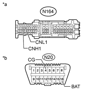
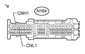
Text in Illustration *a Front view of wire harness connector
(to Multi-media Module Receiver Assembly)
*b Front view of DLC3 Disconnect the multi-media module receiver assembly connector.
-
Measure the resistance according to the value(s) in the table below.
Standard Resistance Tester Connection Condition Specified Condition N164-3 (CNH1) - N164-4 (CNL1) Cable disconnected from negative (-) auxiliary battery terminal 108 to 132 Ω N164-3 (CNH1) - N20-16 (BAT) Cable disconnected from negative (-) auxiliary battery terminal 6 kΩ or higher N164-4 (CNL1) - N20-16 (BAT) Cable disconnected from negative (-) auxiliary battery terminal 6 kΩ or higher N164-3 (CNH1) - N20-4 (CG) Cable disconnected from negative (-) auxiliary battery terminal 200 Ω or higher N164-4 (CNL1) - N20-4 (CG) Cable disconnected from negative (-) auxiliary battery terminal 200 Ω or higher
NG
REPAIR OR REPLACE CAN MAIN WIRE OR CONNECTOR (MULTI-MEDIA MODULE RECEIVER ASSEMBLY - REMOTE TOUCH)
OK
REPLACE MULTI-MEDIA MODULE RECEIVER ASSEMBLY Click here
-
-
CHECK FOR SHORT IN CAN BUS WIRE (ACCESSORY METER ASSEMBLY)
-
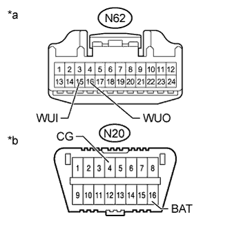
Text in Illustration *a Front view of wire harness connector
(to Accessory Meter Assembly)
*b Front view of DLC3 Disconnect the accessory meter assembly connector.
-
Measure the resistance according to the value(s) in the table below.
Standard Resistance Tester Connection Condition Specified Condition N62-15 (WUI) - N62-16 (WUO) Cable disconnected from negative (-) auxiliary battery terminal 54 to 69 Ω N62-15 (WUI) - N20-16 (BAT) Cable disconnected from negative (-) auxiliary battery terminal 6 kΩ or higher N62-16 (WUO) - N20-16 (BAT) Cable disconnected from negative (-) auxiliary battery terminal 6 kΩ or higher N62-15 (WUI) - N20-4 (CG) Cable disconnected from negative (-) auxiliary battery terminal 200 Ω or higher N62-16 (WUO) - N20-4 (CG) Cable disconnected from negative (-) auxiliary battery terminal 200 Ω or higher
NG
REPAIR OR REPLACE CAN BUS BRANCH WIRE OR CONNECTOR (ACCESSORY METER ASSEMBLY - REMOTE TOUCH)
OK
REPLACE ACCESSORY METER ASSEMBLY Click here
-