STEERING COLUMN ASSEMBLY INSTALLATION

Tech Tips
-
Use the same procedure for RHD and LHD vehicles.
-
The procedure listed below is for LHD vehicles.
-
INSTALL NO. 1 STEERING COLUMN HOLE COVER SUB-ASSEMBLY
-
Install the steering column hole cover with the 2 nuts and 2 bolts.
- Torque:
- 5.0 N*m { 51 kgf*cm, 44 in.*lbf }
-
-
INSTALL STEERING SLIDING WITH SHAFT YOKE SUB-ASSEMBLY
-
Temporarily install the steering sliding with shaft yoke to the No. 2 steering intermediate shaft assembly.
-
-
INSTALL NO. 2 STEERING INTERMEDIATE SHAFT ASSEMBLY
-
Align the matchmarks and install the No. 2 steering intermediate shaft to the steering column assembly.
-
Install the bolt.
- Torque:
- 35 N*m { 360 kgf*cm, 26 ft.*lbf }
-
-
INSTALL STEERING COLUMN ASSEMBLY (TILT STEERING GEAR ASSEMBLY WITH MOTOR)
-
Install the steering column assembly with the 4 nuts.
- Torque:
- 26 N*m { 260 kgf*cm, 19 ft.*lbf }
-
Install the brake pedal return spring.
-
Connect the connectors.
-
-
INSTALL STEERING ACTUATOR ASSEMBLY (w/ VGRS)
-
Make sure that the power steering link assembly is centered.
-
Install the steering actuator assembly.
-
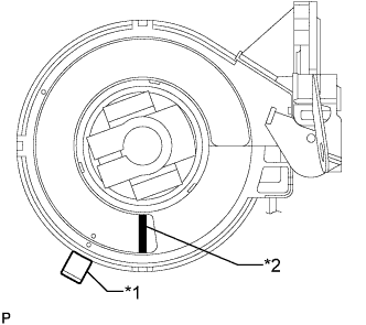
Text in Illustration *1 Center Lock Pin *2 Paint If installing a new steering actuator assembly:
Install a new steering actuator assembly with the white paint on the surface of the spiral case facing downward.
Note
Do not pull out the center lock pin.
-
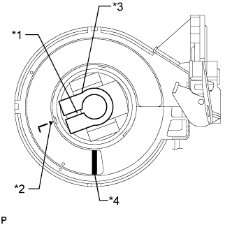
Text in Illustration *1 Slit *2 Alignment Mark *3 Sliding Yoke *4 Paint If reinstalling the removed steering actuator assembly:
-
Slowly turn the spiral case clockwise until it locks.
-
Turn the spiral case two turns counterclockwise from the locked position.
-
Align the slit of the sliding yoke with the alignment mark (▲).
-
Install the steering actuator assembly with the white paint on the surface of the spiral case facing downward.
-
Align the matchmarks on the steering actuator assembly and the column hole shield.
Note
Do not turn the actuator body or spiral case.
-
-
-
Attach the clamp to the steering column hole shield.
-
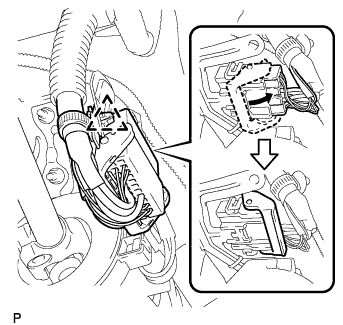
Connect the steering actuator connector.
Tech Tips
Push up the lever until the claw of the steering actuator connector makes a connection sound.
-
Attach the wire harness clamp.
-
-
INSTALL MAIN SHAFT LOWER DUST COVER (w/ VGRS)
-
Install the dust cover with the 2 bolts.
- Torque:
- 7.5 N*m { 76 kgf*cm, 66 in.*lbf }
-
-
CONNECT STEERING SLIDING WITH SHAFT YOKE SUB-ASSEMBLY (w/ VGRS)
-
Align the matchmarks and correct the steering sliding with shaft yoke sub-assembly to the power steering gear assembly.
-
Install the 2 bolts.
- Torque:
- 35 N*m { 360 kgf*cm, 26 ft.*lbf }
-
-
CONNECT STEERING SLIDING WITH SHAFT YOKE SUB-ASSEMBLY (w/o VGRS)
-
Align the matchmark on the steering sliding with shaft yoke with the matchmark on the power steering link and install the bolt.
- Torque:
- 35 N*m { 360 kgf*cm, 26 ft.*lbf }
-
Tighten the bolt of the steering sliding with shaft yoke closest to the vehicle interior.
- Torque:
- 35 N*m { 360 kgf*cm, 26 ft.*lbf }
-
Attach the clamp to the No. 1 steering column hole cover.
-
-
INSTALL NO. 1 AIR DUCT SUB-ASSEMBLY
-
Attach the 2 claws to install the No. 1 air duct sub-assembly with the clip.
-
-
INSTALL NO. 1 INSTRUMENT LOWER PANEL AIRBAG ASSEMBLY
-
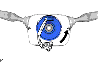
INSTALL TURN SIGNAL SWITCH ASSEMBLY WITH SPIRAL CABLE SUB-ASSEMBLY
-
Attach the 3 claws to install the turn signal switch assembly with spiral cable.
-
Connect the connectors.
-
-
INSTALL STEERING COLUMN COVER (w/ Driver Monitor Camera)
-
Connect the connector.
-
Attach the 2 claws to install the steering column upper cover.
-
Attach the 4 clips.
-
Attach the 2 claws to install the steering column lower cover.
Note
Do not damage the tilt and telescopic switch.
-
Install the 3 screws.
-
-
INSTALL STEERING COLUMN COVER (w/o Driver Monitor Camera)
-
Attach the 2 claws to install the steering column upper cover.
-
Attach the 4 clips.
-
Attach the 2 claws to install the steering column lower cover.
Note
Do not damage the tilt and telescopic switch.
-
Install the 3 screws.
-
-
ADJUST SPIRAL WITH SENSOR CABLE SUB-ASSEMBLY
Note
Do not adjust the spiral cable with the auxiliary battery connected and the power switch on (IG).
-
Check that the power switch is off.
-
Check that the cable is disconnected from the negative (-) auxiliary battery terminal.
CAUTION:
Wait at least 90 seconds after disconnecting the cable from the negative (-) auxiliary battery terminal to disable the SRS system.
-
Check if the spiral cable sub-assembly is centered.
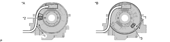
Text in Illustration *A w/o Steering Heater *B w/ Steering Heater *1 Alignment Mark *2 Colored Roller (Yellow) *3 Flat Cable - - Tech Tips
When the spiral cable sub-assembly is centered, the alignment marks are aligned and the colored roller (yellow) or flat cable shown in the illustration is visible.
-
If the spiral cable sub-assembly is not centered, center it.
-
While pushing on the interlock indicated in the illustration, rotate the spiral cable sub-assembly counterclockwise slowly by hand until it stops.
Text in Illustration 
Interlock Note
-
When rotating the spiral cable sub-assembly, make sure to push on the interlock indicated in the illustration to release the interlock mechanism.
-
Do not turn the spiral cable sub-assembly using the airbag wire harness.
-
-

While pushing on the interlock indicated, rotate the spiral cable sub-assembly clockwise approximately 2.5 turns to the position where the colored roller (yellow) or flat cable is visible.
Text in Illustration Interlock Note
-
When rotating the spiral cable sub-assembly, make sure to push on the interlock indicated in the illustration to release the interlock mechanism.
-
Do not turn the spiral cable sub-assembly using the airbag wire harness.
Tech Tips
The spiral cable will rotate approximately 2.5 turns to both the left and right from the center.
-
-
-
INSTALL STEERING WHEEL ASSEMBLY
-
CHECK FRONT WHEELS FACING STRAIGHT AHEAD
-
CONNECT CABLE TO AUXILIARY BATTERY NEGATIVE TERMINAL
Note
-
Reset the auto tilt away function setting to the previous condition by changing the customize parameter Click here.
-
When disconnecting the cable, some systems need to be initialized after the cable is reconnected Click here f).
-
-
CHECK SRS WARNING LIGHT
-
PERFORM VARIABLE GEAR RATIO STEERING SYSTEM CALIBRATION (w/ VGRS)