DYNAMIC REAR STEERING SYSTEM, Diagnostic DTC:C1B13/23

| DTC Code | DTC Name |
|---|---|
| C1B13/23 | Motor Rotation Angle Not Detected |
DESCRIPTION
When the DRS ECU (rear steering control ECU) detects a problem with the motor rotation angle sensor circuit, DTC C1B13/23 is stored.
| DTC Code | DTC Detection Condition | Trouble Area |
|---|---|---|
| C1B13/23 | All conditions are met for approximately 0.2 seconds or more:
|
|
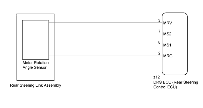
WIRING DIAGRAM
INSPECTION PROCEDURE
Note
-
When replacing the DRS ECU (rear steering control ECU), perform neutral position memorization and motor rotation angle sensor calibration Click here.
-
If the rear steering link assembly or the rear suspension is removed and installed, replaced, or adjusted, after performing actuator calibration value initialization, perform neutral position memorization and motor rotation angle sensor calibration Click here.
-
Since DTC C15C9/76 is stored in the VGRS ECU (front steering control ECU), after performing repairs on the dynamic rear steering system, clear the DTCs for the VGRS system.
PROCEDURE
-
CHECK DTC
-
Check for DTCs Click here.
Result Result Proceed to DTC C1B13/23 is output as a past DTC A DTC C1B13/23 is output as a current DTC B
B 
CHECK FREEZE FRAME DATA (MOTOR RESOLVER SIN PHASE OFFSET, MOTOR RESOLVER COS PHASE OFFSET) Click here
A 
-
-
PERFORM ACTUATOR FORCED ACTIVATION
-
Perform actuator forced activation Click here.
NEXT
-
-
RECONFIRM DTC
-
Check for DTCs Click here.
Result Result Proceed to DTC C1B13/23 is output as a current DTC A DTC C1B13/23 is output as a past DTC B
B 
USE SIMULATION METHOD TO CHECK Click here
A
-
-
CHECK FREEZE FRAME DATA (MOTOR RESOLVER SIN PHASE OFFSET, MOTOR RESOLVER COS PHASE OFFSET)
-
Turn the power switch off.
-
Connect the GTS to the DLC3.
-
Turn the power switch on (IG).
-
Turn the GTS on.
-
Display the DTCs on the GTS screen Click here.
-
Select DTC "C1B13/23", and check the freeze frame data for "Motor Resolver SIN Phase Offset" and "Motor Resolver COS Phase Offset" Click here.
Result Result Proceed to "Motor Resolver SIN Phase Offset" and "Motor Resolver COS Phase Offset" are 5 V or higher A "Motor Resolver SIN Phase Offset" and "Motor Resolver COS Phase Offset" are below 5 V B
B
REPLACE REAR STEERING CONTROL ECU Click here
A
-
-
INSPECT REAR STEERING LINK ASSEMBLY (MOTOR ROTATION ANGLE SENSOR)
-
Turn the power switch off.
-
Disconnect the rear steering link assembly connector from the DRS ECU (rear steering control ECU).
-
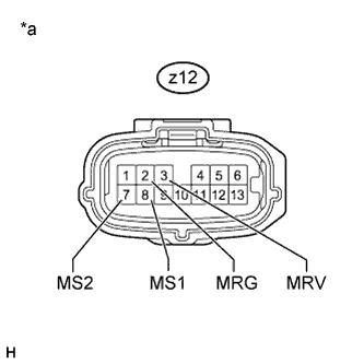
Text in Illustration *a Front view of rear steering link assembly connector
(to DRS ECU [Rear Steering Control ECU])
Measure the resistance according to the value(s) in the table below.
Standard Resistance Tester Connection Condition Specified Condition z12-3 (MRV) - z12-2 (MRG) Always 26 to 64 Ω z12-8 (MS1) - z12-2 (MRG) Always 92 to 230 Ω z12-7 (MS2) - z12-2 (MRG) Always 98 to 247 Ω z12-3 (MRV) - z12-8 (MS1) Always 118 to 294 Ω z12-3 (MRV) - z12-7 (MS2) Always 124 to 311 Ω z12-8 (MS1) - z12-7 (MS2) Always 190 to 477 Ω z12-3 (MRV) - Body ground Always 100 kΩ or higher z12-2 (MRG) - Body ground Always 100 kΩ or higher z12-8 (MS1) - Body ground Always 100 kΩ or higher z12-7 (MS2) - Body ground Always 100 kΩ or higher
NG
REPLACE REAR STEERING LINK ASSEMBLY Click here
OK 
REPLACE REAR STEERING CONTROL ECU Click here
-