VARIABLE GEAR RATIO STEERING SYSTEM, Diagnostic DTC:C15C7/78, C15C8/72

| DTC Code | DTC Name |
|---|---|
| C15C7/78 | DC Motor Power Source Voltage |
| C15C8/72 | DC Motor Power Source Voltage(ECU Start-up) |
DESCRIPTION
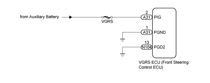
The VGRS ECU (front steering control ECU) monitors terminal PIG (motor power source voltage) in order to detect malfunctions in the power supply relay (located inside the VGRS ECU (front steering control ECU)).
If the VGRS ECU (front steering control ECU) detects a malfunction, it turns on the master warning light, stores these DTCs and stops VGRS operation.
| DTC Code | DTC Detection Condition | Trouble Area |
|---|---|---|
| C15C7/78 | Both conditions are met for approximately 2.4 seconds or more:
|
|
| C15C8/79 | All conditions are met for approximately 1.5 seconds or more:
|
|
WIRING DIAGRAM
INSPECTION PROCEDURE
Note
-
When replacing the VGRS ECU (front steering control ECU), perform actuator angle neutral position calibration and initialization after replacement Click here.
-
Since DTC C1B09/19 is stored in the DRS ECU (rear steering control ECU), after performing repairs on the VGRS system, clear the DTCs for the dynamic rear steering system.
-
Inspect the fuses for circuits related to this system before performing the following inspection procedure.
PROCEDURE
-
READ VALUE USING GTS (PIG POWER SUPPLY VOLTAGE)
-
Turn the power switch off.
-
Connect the GTS to the DLC3.
-
Turn the power switch on (READY).
-
Turn the GTS on.
-
Enter the following menus: Chassis / VGRS / Data List
VGRS Tester Display Measurement Item/Range Normal Condition Diagnostic Note PIG Power Supply Voltage PIG power supply voltage/
Min.: 0.00 V
Max.: 255.99 V
11 to 14 V - OK 11 to 14 V
NG 
INSPECT FRONT STEERING CONTROL ECU (PIG, PGND TERMINAL) Click here
OK 
USE SIMULATION METHOD TO CHECK Click here
-
-
INSPECT FRONT STEERING CONTROL ECU (PIG, PGND TERMINAL)
-
Turn the power switch off.
-
Check the connection of the VGRS ECU (front steering control ECU) connector and the condition of the terminals.
-
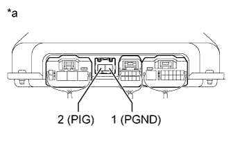
Text in Illustration *a Component without harness connected
(VGRS ECU [Front Steering Control ECU])
Disconnect the A31 VGRS ECU (front steering control ECU) connector.
-
Measure the resistance according to the value(s) in the table below.
Standard Resistance Tester Connection Condition Specified Condition 2 (PIG) - 1 (PGND) Always 100 kΩ or higher
B 
REPLACE FRONT STEERING CONTROL ECU Click here
A 
-
-
CHECK HARNESS AND CONNECTOR (PGND, PGD2 TERMINAL)
-
Turn the power switch off.
-
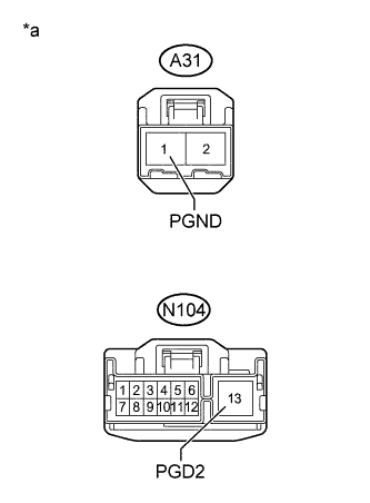
Text in Illustration *a Front view of wire harness connector
(to VGRS ECU [Front Steering Control ECU])
Disconnect the VGRS ECU (front steering control ECU) connector.
-
Measure the resistance according to the value(s) in the table below.
Standard Resistance Tester Connection Switch Condition Specified Condition A31-1 (PGND) - Body ground Power switch off Below 1 Ω N104-13 (PGD2) - Body ground Power switch off Below 1 Ω
NG
REPAIR OR REPLACE HARNESS OR CONNECTOR
OK
-
-
CHECK HARNESS AND CONNECTOR (PIG, PGND TERMINAL)
-
Turn the power switch off.
-
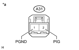
Text in Illustration *a Front view of wire harness connector
(to VGRS ECU [Front Steering Control ECU])
Disconnect the VGRS ECU (front steering control ECU) connector.
-
Measure the voltage according to the value(s) in the table below.
Standard Voltage Tester Connection Switch Condition Specified Condition A31-2 (PIG) - A31-1 (PGND) Power switch off 11 to 14 V Result Result Proceed to The voltage is in the range of 11 to 14 V A The voltage is below 11 V B The voltage is higher than 14 V C
B
REPAIR OR REPLACE HARNESS OR CONNECTOR
C
CHECK OR REPLACE CHARGING SYSTEM OR AUXILIARY BATTERY Click here
A
REPLACE FRONT STEERING CONTROL ECU Click here
-