VARIABLE GEAR RATIO STEERING SYSTEM, Diagnostic DTC:C1597/57

| DTC Code | DTC Name |
|---|---|
| C1597/57 | Lost Communication between VGRS and DRS |
DESCRIPTION
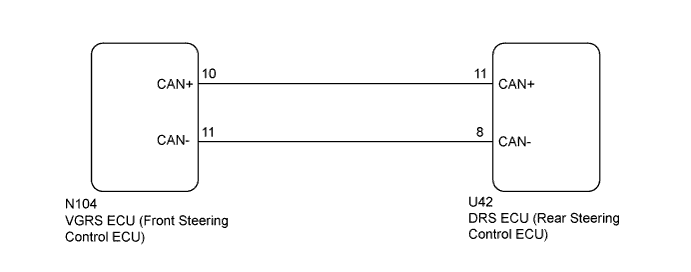
The VGRS ECU (front steering control ECU) communicates with the DRS ECU (rear steering control ECU) via the local bus.
| DTC Code | DTC Detection Condition | Trouble Area |
|---|---|---|
| C1597/57 | All conditions are met for approximately 3 seconds or more:
|
|
WIRING DIAGRAM
INSPECTION PROCEDURE
Note
-
When replacing the DRS ECU (rear steering control ECU), perform neutral position memorization and motor rotation angle sensor calibration Click here.
-
When replacing the VGRS ECU (front steering control ECU), perform actuator angle neutral position calibration and initialization after replacement Click here.
PROCEDURE
-
CHECK FOR DTC (DYNAMIC REAR STEERING SYSTEM)
-
Check for DTCs in the dynamic rear steering system Click here.
Result Result Proceed to DTC U0130/41 is not output A DTC U0130/41 is output B
B 
GO TO DYNAMIC REAR STEERING SYSTEM (DIAGNOSTIC TROUBLE CODE CHART) Click here
A 
-
-
CHECK FOR DTC
-
Check for DTCs Click here.
Result Result Proceed to DTC U0134/56 is not output A DTC U0134/56 is output B
B
GO TO DIAGNOSTIC TROUBLE CODE CHART Click here
A
-
-
CHECK HARNESS AND CONNECTOR (CAN+, CAN- TERMINAL)
-
Turn the power switch off.
-
Check the connection of the VGRS ECU (front steering control ECU) connector and the condition of the terminals.
-
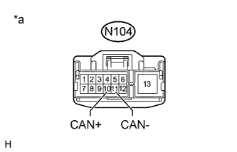
Text in Illustration *a Front view of wire harness connector
(to VGRS ECU [Front Steering Control ECU])
Disconnect the VGRS ECU (front steering control ECU) connector.
-
Measure the resistance according to the value(s) in the table below.
Tech Tips
Measure the resistance of the DRS ECU (rear steering control ECU) and wire harness from the connector of the VGRS ECU (front steering control ECU).
Standard Resistance Tester Connection Condition Specified Condition N104-10 (CAN+) - N104-11 (CAN-) Always 100 to 140 Ω N104-10 (CAN+) - Body ground Always 100 kΩ or higher N104-11 (CAN-) - Body ground Always 100 kΩ or higher
NG 
INSPECT REAR STEERING CONTROL ECU (CAN+, CAN- TERMINAL) Click here
OK
-
-
INSPECT FRONT STEERING CONTROL ECU (CAN+, CAN- TERMINAL)
-
Turn the power switch off.
-
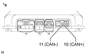
Text in Illustration *a Component without harness connected
(VGRS ECU [Front Steering Control ECU])
Disconnect the N104 VGRS ECU (front steering control ECU) connector.
-
Measure the resistance according to the value(s) in the table below.
Standard Resistance Tester Connection Condition Specified Condition 10 (CAN+) - 11 (CAN-) Always 100 to 140 Ω 10 (CAN+) - Body ground Always 100 kΩ or higher 11 (CAN-) - Body ground Always 100 kΩ or higher
NG
REPLACE FRONT STEERING CONTROL ECU Click here
OK
-
-
RECONFIRM DTC
-
Reconnect the N104 VGRS ECU (front steering control ECU) connector.
-
Clear the DTCs Click here.
-
Check for DTCs Click here.
Result Result Proceed to DTC C1597/57 is not output A DTC C1597/57 is output B
B
REPLACE FRONT STEERING CONTROL ECU Click here
A 
USE SIMULATION METHOD TO CHECK Click here
-
-
INSPECT REAR STEERING CONTROL ECU (CAN+, CAN- TERMINAL)
-
Turn the power switch off.
-
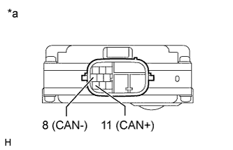
Text in Illustration *a Component without harness connected
(DRS ECU [Rear Steering Control ECU])
Disconnect the U42 DRS ECU (rear steering control ECU) connector.
-
Measure the resistance according to the value(s) in the table below.
Standard Resistance Tester Connection Condition Specified Condition 11 (CAN+) - 8 (CAN-) Always 100 to 140 Ω 11 (CAN+) - Body ground Always 100 kΩ or higher 8 (CAN-) - Body ground Always 100 kΩ or higher
NG
REPLACE REAR STEERING CONTROL ECU Click here
OK
REPAIR OR REPLACE HARNESS OR CONNECTOR
-