DC / DC CONVERTER (for 2GR-FXE) REMOVAL

Tech Tips
-
Use the same procedure for RHD and LHD vehicles.
-
The procedure listed below is for LHD vehicles.
-
PRECAUTION
Note
After turning the power switch off, waiting time may be required before disconnecting the cable from the auxiliary battery terminal. Therefore, make sure to read the disconnecting the cable from the auxiliary battery terminal notice before proceeding with work Click here.
-
REMOVE LUGGAGE COMPARTMENT FLOOR MAT
-
Remove the luggage compartment floor mat.
-
-
REMOVE LUGGAGE COMPARTMENT TRIM COVER LH
-
Remove the luggage compartment trim cover.
-
-
DISCONNECT CABLE FROM AUXILIARY BATTERY TERMINAL
Note
When disconnecting the cable, some systems need to be initialized after the cable is reconnected Click here.
-
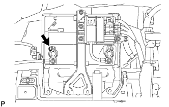
Disconnect the cable from the auxiliary battery negative (-) terminal.
Tech Tips
Both cables should be disconnected to prevent the AMD terminal from shorting to ground.
-
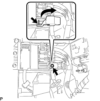
Remove the terminal cover.
-
Remove the nut and disconnect the cable from the auxiliary battery positive (+) terminal.
Tech Tips
Both cables should be disconnected to prevent the AMD terminal from shorting to ground.
-
-
REMOVE NO. 1 SEAT ARMREST CAP
-
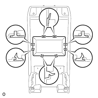
Detach the 4 claws and 4 guides, and remove the No. 1 seat armrest cap.
-
-
REMOVE HYBRID VEHICLE BATTERY LOWER COVER PANEL
CAUTION:
Perform work using insulated gloves and insulated tools.
-
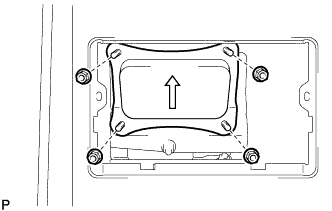
Remove the 4 nuts and lower hybrid vehicle battery cover panel.
-
-
REMOVE SERVICE PLUG GRIP
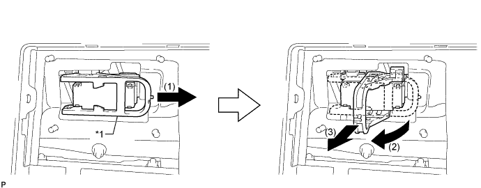
Text in Illustration *1 Lever - -
-
Remove the service plug grip in the order shown in the illustration.
CAUTION:
-
Wear insulated gloves.
-
Remove the service plug grip to interrupt a high voltage circuit at the time of the check.
-
Keep the removed service plug grip in your pocket to prevent other technicians from accidentally reconnecting it while you are servicing the vehicle.
-
After disconnecting the service plug grip, wait for at least 10 minutes before touching any of the high-voltage connectors or terminals.
-
Never turn the power switch on (READY) with the service plug grip removed as malfunctions may occur.
Tech Tips
-
Waiting for at least 10 minutes is required to discharge the high-voltage capacitor inside the inverter with converter assembly.
-
High voltage wiring connectors are orange.
-
Slide the lever and release the lock.
-
Raise the lever and pull the service plug grip to remove it.
-
-
-
REMOVE INVERTER COVER
-
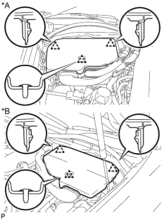
Text in Illustration *A for LHD *B for RHD Raise the front of the inverter cover to detach the clip. Then remove the 2 inverter cover clips from the bracket, and remove the inverter cover.
-
-
REMOVE CONNECTOR COVER ASSEMBLY
CAUTION:
-
Do not touch the high voltage connectors and terminals for 10 minutes after the service plug grip is removed.
-
Wear insulated gloves.
Note
Do not start the hybrid system with the service plug grip removed because it may cause a malfunction.
-
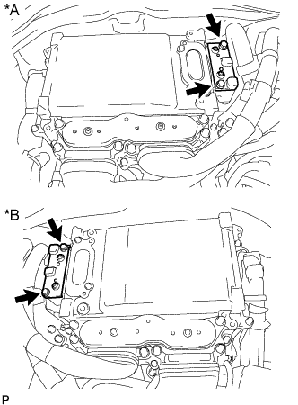
Text in Illustration *A for LHD *B for RHD Using an insulated tool, remove the 2 bolts and connector cover.
Note
-
Make sure to pull the connector cover straight up, as a connector is connected to the bottom of the cover.
-
Do not allow any foreign objects or water to enter the inverter with converter.
-
-
-
CHECK TERMINAL VOLTAGE
CAUTION:
Wear insulated gloves.
Note
Do not allow any foreign objects or water to enter the inverter with converter assembly.
-
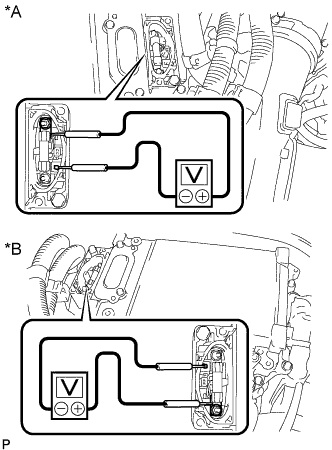
Text in Illustration *A for LHD *B for RHD Using a voltmeter, measure the voltage between the terminals of the 2 phase connectors.
Standard voltage 0 V Tech Tips
Use a measuring range of DC 750 V or more on the voltmeter.
-
-
INSTALL CONNECTOR COVER ASSEMBLY
CAUTION:
Wear insulated gloves.
Note
-
Make sure that the interlock is fully engaged.
-
Do not allow any foreign objects or water to enter the inverter with converter.
-
Using an insulated tool, install the connector cover with the 2 bolts.
- Torque:
- 8.0 N*m { 82 kgf*cm, 71 in.*lbf }
-
-
INSTALL INVERTER COVER
-
Attach the 2 inverter cover claws to the inverter with converter. Then attach the inverter cover with the clip.
-
-
REMOVE FRONT LUGGAGE COMPARTMENT TRIM COVER
-
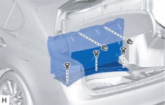
Remove the 3 clips, 2 nuts and front luggage compartment trim cover.
-
-
REMOVE ECU BRACKET
CAUTION:
Perform work using insulated gloves and insulated tools.
-
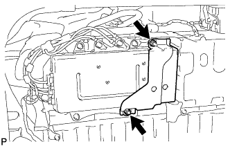
Remove the 2 nuts and ECU bracket.
-
-
REMOVE POWER STEERING CONVERTER ASSEMBLY
CAUTION:
Perform work using insulated gloves and insulated tools.
-
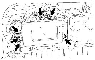
Remove the 2 bolts and disconnect the 2 harness cables.
-
Disconnect the 4 connectors.
Note
-
Insulate the connectors of the disconnected high voltage wires with insulating tape.
-
High voltage wiring connectors are orange.
-
-

Remove the 3 nuts and power steering converter assembly.
-