POWER STEERING SYSTEM (for 2GR-FXE) TERMINALS OF ECU

-
TERMINALS OF ECU
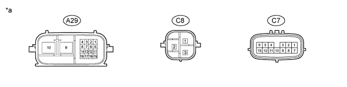
Text in Illustration *a Component with harness connected
(Power Steering ECU)
- - Tech Tips
The power steering ECU uses waterproof connectors. Therefore, voltage or waveforms cannot be checked with the connectors connected to the vehicle.
Terminal No. (Symbol) Wiring Color Terminal Description A29-2 (CA1L) W*1
B*2
Low-level CAN bus line A29-3 (CA1H) B*1
W*2
High-level CAN bus line A29-4 (CA3H) W High-level CAN bus line A29-5 (TS) R TS signal A29-6 (CA3L) B Low-level CAN bus line A29-7 (WDD1) GR DC / DC warning input signal A29-8 (+B) Y Auxiliary battery power A29-9 (PGND) B Power ground A29-10 (PIG) W Power source A29-13 (ASST) P DC / DC demand output signal A29-14 (IG) B IG power source C7-1 (RZG) B Motor rotation angle sensor power source circuit ground C7-2 (SRZG) BR Motor rotation angle sensor shield ground C7-3 (RZV) G Motor rotation angle sensor power source C7-4 (TRQV) W Torque sensor power source C7-6 (TQG1) L-W Torque sensor power source circuit ground C7-7 (RZSN) R SIN phase input signal (Motor rotation angle sensor) C7-8 (RZCS) W COS phase input signal (Motor rotation angle sensor) C7-9 (INSN) G-W SIN phase input signal (Torque sensor input shaft side) C7-10 (INCS) R-L COS phase input signal (Torque sensor input shaft side) C7-11 (OUSN) G-B SIN phase input signal (Torque sensor output shaft side) C7-12 (OUCS) Y-B COS phase input signal (Torque sensor output shaft side) C7-13 (TQG2) R-B Torque sensor detection circuit ground C8-1 (V) W V phase motor output C8-2 (W) B W phase motor output C8-3 (U) R U phase motor output
-
*1: for LHD
-
*2: for RHD
-
-
CHECK WIRE HARNESS SIDE CONNECTOR
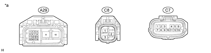
Text in Illustration *a Front view of wire harness connector
(to Power Steering ECU)
- -
-
Disconnect the power steering ECU connectors.
-
Measure the voltage and resistance according to the value(s) in the table below.
Terminal No. (Symbol) Wiring Color Terminal Description Condition Specified Condition A29-8 (+B) - Body ground Y - Body ground Auxiliary battery power Always 11 to 14 V A29-9 (PGND) - Body ground B - Body ground Power ground Always Below 1 Ω A29-14 (IG) - Body ground B - Body ground IG power source Power switch on (IG) 11 to 14 V C8-1 (V) - C8-3 (U) or C8-2 (W) W - R or B V phase motor output Always Below 1 Ω C8-2 (W) - C8-3 (U) or C8-1 (V) B - R or W W phase motor output Always Below 1 Ω C8-3 (U) - C8-2 (W) or C8-1 (V) R - B or W U phase motor output Always Below 1 Ω
-