ELECTRIC PARKING BRAKE SYSTEM, Diagnostic DTC:C13AD/23

| DTC Code | DTC Name |
|---|---|
| C13AD/23 | Open in +B Circuit |
DESCRIPTION
| DTC Code | Detection Condition | Trouble Area |
|---|---|---|
| C13AD/23 | All of following conditions are met:
|
|
-
*1: This value is based on the assumption that the auxiliary battery voltage is 12 V.
-
*2: EPB stands for Electric Parking Brake.
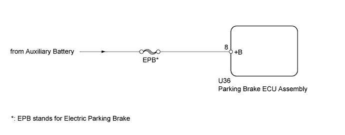
WIRING DIAGRAM
INSPECTION PROCEDURE
Note
-
If the parking brake ECU assembly is replaced, perform the "Reset Memory" and "Acquire Tension Sensor Zero Point" procedures Click here.
-
Before disconnecting connectors or fuses, turn the power switch off and wait 20 seconds or more.
-
Inspect the fuses for circuits related to this system before performing the following inspection procedure.
PROCEDURE
-
CHECK HARNESS AND CONNECTOR (PARKING BRAKE ECU ASSEMBLY - BATTERY)
-
Disconnect the parking brake ECU assembly connector.
-
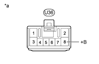
Text in Illustration *a Front view of wire harness connector
(to Parking Brake ECU Assembly)
Measure the voltage according to the value(s) in the table below.
Standard Voltage Tester Connection Condition Specified Condition U36-8 (+B) - Body ground Always 11 to 14 V
NG 
REPAIR OR REPLACE HARNESS OR CONNECTOR
OK 
-
-
READ VALUE USING GTS (+B VOLTAGE VALUE)
-
Turn the power switch off.
-
Connect the GTS to the DLC3.
-
Turn the power switch on (IG) and the GTS on.
-
Enter the following menus: Chassis / Electric Parking Brake / Data List.
-
Check the values by referring to the table below.
Electric Parking Brake Tester Display Measurement Item/Range Switch Condition Normal Condition +B Voltage Value Electric parking brake motor power source information display/
Lo, Mid or Hi
Power switch on (IG) Hi OK Values are as shown in normal condition.
NG
REPLACE PARKING BRAKE ECU ASSEMBLY Click here
OK 
USE SIMULATION METHOD TO CHECK Click here
-