ELECTRIC PARKING BRAKE SYSTEM, Diagnostic DTC:C13A2/22

| DTC Code | DTC Name |
|---|---|
| C13A2/22 | Engine / Power Switch Malfunction |
DESCRIPTION
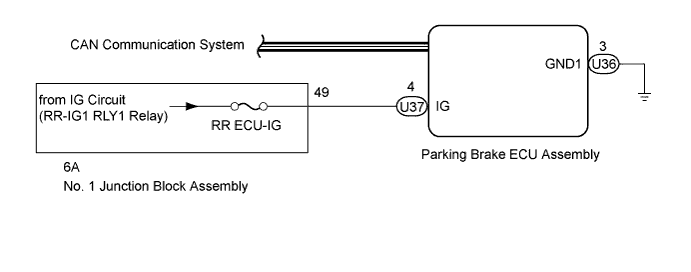
When the power switch is turned to on (IG), this turns on the RR-IG1 RLY1 relay built into the No. 1 junction block assembly. Power is then supplied to the parking brake ECU assembly from the auxiliary battery.
| DTC No. | Detection Condition | Trouble Area |
|---|---|---|
| C13A2/22 | Both of the following conditions are met:
|
|
WIRING DIAGRAM
INSPECTION PROCEDURE
Note
-
If the parking brake ECU assembly or parking brake with bracket actuator assembly is replaced, perform the "Reset Memory" and "Acquire Tension Sensor Zero Point" procedures Click here.
-
Before disconnecting connectors or fuses, turn the power switch off and wait 20 seconds or more.
-
Inspect the fuses for circuits related to this system before performing the following inspection procedure.
PROCEDURE
-
READ VALUE USING GTS (IG STATUS/IG SWITCH)
-
Turn the power switch off.
-
Connect the GTS to the DLC3.
-
Turn the power switch on (IG) and the GTS on.
-
Enter the following menus: Chassis / Electric Parking Brake / Data List.
-
Check the values by referring to the table below.
Electric Parking Brake Tester Display Measurement Item/Range Normal Condition Diagnostic Note IG Status Power switch information display/
ON or OFF
ON: Power switch is on (IG)
OFF: Power switch is on (ACC) or off
IG circuit IG Switch IG power source information display/
ON or OFF
ON: IG power source is input into parking brake ECU assembly
OFF: IG power source is not input into parking brake ECU assembly
IG circuit OK When the power switch is on (IG), items on the GTS are ON.
NG 
CHECK HARNESS AND CONNECTOR (PARKING BRAKE ECU - NO. 1 JUNCTION BLOCK) Click here
OK 
-
-
CLEAR DTC
-
Clear the DTCs Click here.
NEXT
-
-
CHECK DTC
-
Check for DTCs Click here.
Result Result Proceed to DTC C13A2/22 is output A DTC C13A2/22 is not output B
B 
USE SIMULATION METHOD TO CHECK Click here
A 
REPLACE PARKING BRAKE ECU ASSEMBLY Click here
-
-
CHECK HARNESS AND CONNECTOR (PARKING BRAKE ECU - NO. 1 JUNCTION BLOCK)
-
Disconnect the U36 and U37 parking brake ECU assembly connectors.
-
Disconnect the 6A No. 1 junction block assembly connector.
-
Measure the resistance according to the value(s) in the table below.
Standard Resistance Tester Connection Condition Specified Condition U37-4 (IG) - 6A-49 Always Below 1 Ω U37-4 (IG) - Body ground Always 10 kΩ or higher U36-3 (GND1) - Body ground Always Below 1 Ω
NG
REPAIR OR REPLACE HARNESS OR CONNECTOR
OK
REPAIR IG POWER SOURCE CIRCUIT
-