REAR BRAKE INSTALLATION

Tech Tips
-
Use the same procedure for the RH and LH sides.
-
The procedure listed below is for the LH side.
-
INSTALL REAR DISC
-

Text in Illustration *a Matchmark Align the matchmarks of the rear disc and axle hub and install the rear disc.
Note
When replacing the rear disc with a new one, select the installation position where the rear disc has the smallest runout.
-
-
INSTALL PARKING BRAKE SHOE ADJUSTING HOLE PLUG
-
INSTALL REAR NO. 1 DISC BRAKE CALIPER PLATE
-
Install 2 new rear No. 1 disc brake caliper plates to the disc brake cylinder mounting.
-
-
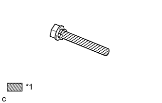
INSTALL DISC BRAKE CYLINDER MOUNTING LH
-
Install the disc brake cylinder mounting to the rear axle with the 2 bolts.
- Torque:
- 125 N*m { 1275 kgf*cm, 92 ft.*lbf }
-
-
INSTALL REAR DISC BRAKE BUSH DUST BOOT
-
Text in Illustration *1 Lithium soap base glycol grease Apply a light coat of lithium soap base glycol grease to the entire circumference of 2 new rear disc brake bush dust boots where they contact the disc brake cylinder mounting, and the entire inner circumference of both ends of the rear disc brake bush dust boots.
Tech Tips
Apply at least 0.3 g (0.01 oz.) of lithium soap base glycol grease to the rear disc brake bush dust boot.
Note
Apply a sufficient amount of lithium soap base glycol grease to the entire circumference of the rear disc brake bush dust boot and disc brake cylinder mounting contact surfaces.
-
Install the 2 rear disc brake bush dust boots to the disc brake cylinder mounting.
-
-
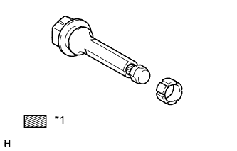
INSTALL REAR NO. 1 DISC BRAKE CYLINDER SLIDE PIN
-
Text in Illustration *1 Lithium soap base glycol grease Apply a light coat of lithium soap base glycol grease to the sliding and sealing surfaces of the rear No. 1 disc brake cylinder slide pin.
-
Install the rear No. 1 disc brake cylinder slide pin to the disc brake cylinder mounting.
-
Push the rear No. 1 brake cylinder slide pin into the rear disc brake bush dust boot to engage the rear No. 1 disc brake cylinder slide pin to the rear disc brake bush dust boot.
-
-
INSTALL REAR DISC BRAKE CYLINDER SLIDE BUSH
-
Text in Illustration *1 Lithium soap base glycol grease Apply a light coat of lithium soap base glycol grease to the rear disc brake rear cylinder slide pin as shown in the illustration.
-
Install a new rear disc brake cylinder slide bush to the rear disc brake rear cylinder slide pin.
-
-
INSTALL REAR DISC BRAKE REAR CYLINDER SLIDE PIN
-
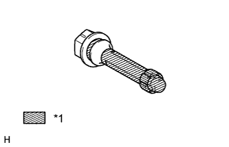
Text in Illustration *1 Lithium soap base glycol grease Apply a light coat of lithium soap base glycol grease to the sliding part and the seal surface of the rear disc brake rear cylinder slide pins.
-
Install the rear disc brake rear cylinder slide pins to the disc brake cylinder mounting.
-
Push the rear disc brake rear cylinder slide pin into the rear disc brake bushing dust boot to engage the rear disc brake rear cylinder slid pin to the rear disc brake bush dust boot.
-
-
INSTALL REAR NO. 1 DISC BRAKE PAD SUPPORT PLATE
-
Clean the contact surfaces of the rear No. 1 disc brake pad support plates, rear No. 2 disc brake pad support plates, disc brake cylinder mounting and rear disc brake pads with brake cleaner.
-
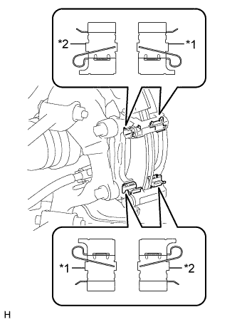
Text in Illustration *1 Rear No. 1 Disc Brake Pad Support Plate *2 Rear No. 2 Disc Brake Pad Support Plate Install the 2 rear No. 1 disc brake pad support plates to the disc brake cylinder mounting.
Note
-
As the rear No. 1 disc brake pad support plates and rear No. 2 disc pad support plates have a different shape, be sure to check the part number and shape to confirm the installation location before installing a new pad support plate.
-
When reusing the rear No. 1 disc brake pad support plates or rear No. 2 disc pad support plates, check the identification marks that were made when removing the pad support plates before installing them.
-
-
-
INSTALL REAR NO. 2 DISC BRAKE PAD SUPPORT PLATE
-
Install the 2 rear No. 2 disc brake pad support plates to the disc brake cylinder mounting.
Note
-
As the rear No. 1 disc brake pad support plates and rear No. 2 disc pad support plates have a different shape, be sure to check the part number and shape to confirm the installation location before installing a new pad support plate.
-
When reusing the rear No. 1 disc brake pad support plates or rear No. 2 disc pad support plates, check the identification marks that were made when removing the pad support plates before installing them.
-
-
-
INSTALL REAR DISC BRAKE ANTI-SQUEAL SHIM KIT
-
Install the 2 pad wear indicator plates to the rear disc brake pads.
Note
-
Install the 2 pad wear indicator plate in the correct positions and facing the correct directions.
-
Install the rear disc brake pads with the pad wear indicator plates on the bottom.
-
-
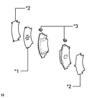
Text in Illustration *1 Rear No. 1 Anti-squeal Shim *2 Rear No. 2 Anti-squeal Shim *3 Pad Wear Indicator Plate Install the No. 1 anti-squeal shim and No. 2 anti-squeal shim to each pad.
Note
When the pads are replaced with new ones, also replace the anti-squeal shims with new ones.
-
-
INSTALL REAR DISC BRAKE PAD
-
Install the 2 rear disc brake pads to the disc brake cylinder mounting.
Note
Make sure there is no oil or grease on the friction surfaces of the rear disc brake pads or the rear disc.
-
-
INSTALL REAR DISC BRAKE CYLINDER ASSEMBLY
-
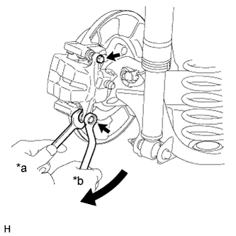
Text in Illustration *a Hold *b Turn Hold the rear disc brake cylinder slide pins and install the rear disc brake cylinder assembly to the disc brake cylinder mounting with 2 new bolts.
- Torque:
- 27 N*m { 270 kgf*cm, 20 ft.*lbf }
-
-
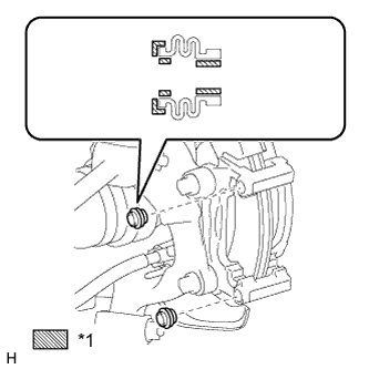
CONNECT REAR FLEXIBLE HOSE LH
-
Install a new gasket and connect the rear flexible hose to the rear disc brake cylinder assembly with a union bolt.
- Torque:
- 39 N*m { 400 kgf*cm, 29 ft.*lbf }
Tech Tips
Insert the flexible hose lock securely into the lock hole in the disc brake cylinder.
-
-
BLEED BRAKE LINE
CAUTION:
If the brake fluid is replaced without using the GTS, the procedure will be incomplete which could lead to problems or accidents. Always use the GTS when performing fluid replacement.
-
Bleed air from the brake lines.
-
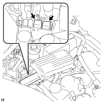
Remove the 2 ABS motor relays.
Tech Tips
If the ABS relays are already removed, this procedure is unnecessary.
-
Remove the brake master cylinder reservoir filler cap assembly.
-
Add brake fluid so that the fluid level is between the MIN and MAX lines of the brake fluid reservoir.
Brake fluid SAE J1703 or FMVSS No. 116 DOT 3 -
With the power switch off, connect the GTS to the DLC3.
-
Turn the power switch on (IG), turn the GTS on, and enter the following menus: Chassis / ABS/VSC/TRC / Utility / ECB (Electronically Controlled Brake system) Invalid.
-
Repeatedly depress the brake pedal to bleed the air from the bleeder plug of the front disc brake cylinder RH.
Note
Add fluid so that the fluid level does not drop below the MIN line on the brake fluid reservoir.
-
After bleeding the air, depress and hold the brake pedal, and tighten the bleeder plug.
- Torque:
- 11 N*m { 110 kgf*cm, 8 ft.*lbf }
-
In the same way as the RH side, bleed air from the bleeder plug of the front disc brake cylinder LH.
-
Follow the GTS screen, to end ECB (Electronically Controlled Brake system) Invalid.
-
Install the 2 ABS motor relays with the power switch off.
-
Turn the power switch on (IG), turn the GTS on, and enter the following menus: Chassis / ABS/VSC/TRC / Utility / ECB (Electronically Controlled Brake system) Invalid.
-
While depressing the brake pedal, loosen the bleeder plug of the rear disc brake cylinder LH. While the pump motor and solenoid are operating, bleed the air.
Note
Add fluid so that the fluid level does not drop below the MIN line on the brake fluid reservoir.
-
After bleeding the air, tighten the bleeder plug and release the brake pedal.
- Torque:
- 8.3 N*m { 85 kgf*cm, 73 in.*lbf }
-
In the same way as the LH side, bleed air from the bleeder plug of the rear disc brake cylinder RH.
-
Follow the GTS screen to end ECB (Electronically Controlled Brake system) Invalid.
-
-
Clear DTCs Click here.
-
Turn the GTS off and turn the power switch off.
-
Check for brake fluid leaks.
-
Inspect and adjust the brake fluid level in the reservoir Click here.
-
-
ADJUST PARKING BRAKE
-
INSTALL REAR WHEEL
- Torque:
- 103 N*m { 1050 kgf*cm, 76 ft.*lbf }