BRAKE PEDAL STROKE SENSOR INSTALLATION

Tech Tips
-
Use the same procedure for the RHD and LHD vehicles.
-
The procedure listed below is for the LHD vehicles.
Note
-
While the auxiliary battery is connected, even if the power switch is off, the brake control system activates when the brake pedal is depressed or the driver door courtesy switch is turned on. Therefore, when servicing brake system components, do not depress the brake pedal or open/close the doors while the auxiliary battery is connected.
-
Do not drop the brake pedal stroke sensor assembly.
-
If the brake pedal stroke sensor assembly has been dropped, replace the brake pedal stroke sensor assembly with a new one.
-
CHECK AND ADJUST BRAKE PEDAL HEIGHT
Tech Tips
Check and adjust the brake pedal height with the floor carpet folded back.
-
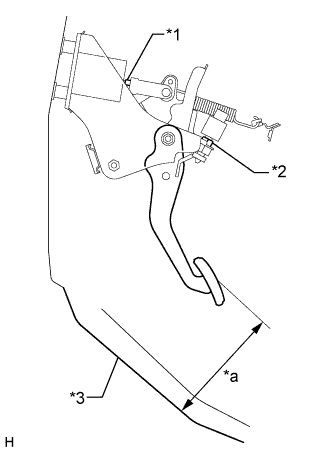
Text in Illustration *1 Clevis Lock Nut *2 Stop Light Switch Lock Nut *3 Floor Panel *a Pedal Height Check the brake pedal height.
Standard pedal height from floor panel 158.4 to 168.4 mm (6.24 to 6.62 in.) -
Adjust the brake pedal height.
-
Disconnect the connector from the stop light switch assembly.
-
Loosen the stop light switch to allow for pedal free play.
-
Loosen the push rod clevis lock nut.
-
Adjust the pedal height by turning the push rod.
Standard pedal height from floor panel 158.4 to 168.4 mm (6.24 to 6.62 in.) -
Tighten the push rod clevis lock nut.
- Torque:
- 26 N*m { 265 kgf*cm, 19 ft.*lbf }
-
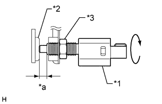
Text in Illustration *1 Stop Light Switch *2 Cushion *3 Stop Light Switch Lock Nut *a 0.87 to 2.4 mm (0.0343 to 0.0944 in.) Check the switch clearance.
Standard stop light switch clearance 0.87 to 2.4 mm (0.0343 to 0.0944 in.) -
Tighten the stop light switch lock nut.
- Torque:
- 17 N*m { 173 kgf*cm, 13 ft.*lbf }
Note
Do not depress the pedal.
-
-
-
INSTALL BRAKE PEDAL STROKE SENSOR ASSEMBLY
-
When installing a new brake pedal stroke sensor assembly:
Note
Do not brake the brake pedal stroke sensor assembly lever set pin before installing the brake pedal stroke sensor assembly with the 2 nuts.
-
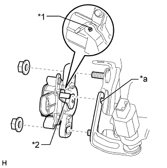
Text in Illustration *1 Pin *2 Lever *a Groove Install a new brake pedal stroke sensor assembly to the brake pedal support assembly with the 2 nuts.
- Torque:
- 8.5 N*m { 87 kgf*cm, 75 in.*lbf }
Note
-
Engage the brake pedal stroke sensor assembly lever with the brake pedal groove.
-
Check that there is no foreign matter attached to the contact surface of the brake pedal stroke sensor assembly.
-
Check that the tip of the brake pedal stroke sensor assembly lever is protruding from the brake pedal groove.
-
Strongly depress the brake pedal to break the brake pedal stroke sensor assembly lever set pin.
-
Remove the broken lever set pin.
-
Connect the connector to the brake pedal stroke sensor assembly.
-
-
When reusing the brake pedal stroke sensor assembly:
-
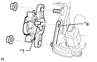
Text in Illustration *1 Lever *a Groove Temporarily install the brake pedal stroke sensor assembly to the brake pedal support assembly with the 2 nuts.
Note
-
Engage the brake pedal stroke sensor assembly lever with the brake pedal groove.
-
Check that there is no foreign matter attached to the contact surface of the brake pedal stroke sensor assembly.
-
Check that the tip of the brake pedal stroke sensor assembly lever is protruding from the brake pedal groove.
Tech Tips
Tighten the 2 nuts after adjusting the installation position.
-
-
Connect the connector to the brake pedal stroke sensor assembly.
-
-
-
CHECK AND ADJUST BRAKE PEDAL STROKE SENSOR ASSEMBLY
Note
When the brake pedal stroke sensor assembly is being reused, perform the following procedure to adjust it.
-
Connect the cable to the auxiliary battery negative (-) terminal.
-
Connect the GTS to the DLC3 with the power switch off.
-
Turn the power switch on (IG).
-
Turn the GTS on.
-
Enter the following menus: Chassis / ABS/VSC/TRC / Date List / Stroke Sensor.
-
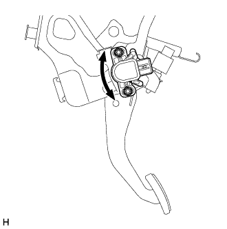
Reading the stroke sensor a value shown in the Date List, slowly turn the brake pedal stroke sensor assembly to the right and left so that it is within the following range.
Standard voltage (without the brake pedal depressed) 0.8 to 1.2 V -
Tighten the 2 nuts.
- Torque:
- 8.5 N*m { 87 kgf*cm, 75 in.*lbf }
Note
Do not depress the brake pedal after turning the power switch on (IG).
-
Turn the GTS off and turn the power switch off.
-
Disconnect the GTS from the DLC3.
-
Disconnect the cable from the auxiliary battery negative (-) terminal.
-
-
INSTALL LOWER NO. 1 INSTRUMENT PANEL AIRBAG ASSEMBLY
-
CONNECT CABLE TO AUXILIARY BATTERY NEGATIVE TERMINAL
Note
When disconnecting the cable, some systems need to be initialized after the cable is reconnected Click here.
-
INSTALL LUGGAGE COMPARTMENT TRIM COVER LH
-
Install the luggage compartment trim cover LH.
-
-
INSTALL LUGGAGE COMPARTMENT FLOOR MAT
-
Install the luggage compartment floor mat.
-
-
CHECK SRS WARNING LIGHT
-
CHECK AND CLEAR DTC
-
PERFORM INITIALIZATION AND CALIBRATION OF LINEAR SOLENOID VALVE