BRAKE ACTUATOR INSTALLATION

Tech Tips
-
Use the same procedure for the RHD and LHD vehicles.
-
The procedure listed below is for the LHD vehicles.
Note
While the auxiliary battery is connected, even if the power switch is off, the brake control system activates when the brake pedal is depressed or the driver door courtesy switch is turned on. Therefore, when servicing brake system components, do not depress the brake pedal or open/close the doors while the auxiliary battery is connected.
-
INSTALL NO. 5 BRAKE ACTUATOR BRACKET
-
Install the No. 5 brake actuator bracket to the body with the bolt.
- Torque:
- 11 N*m { 112 kgf*cm, 8 ft.*lbf }
-
-
INSTALL BRAKE ACTUATOR WITH BRACKET
-
Install the brake actuator with bracket with the 2 bolts and nut. Tighten the 2 bolts and nut uniformly in alphabetical order.
- Torque:
- 19 N*m { 194 kgf*cm, 14 ft.*lbf }
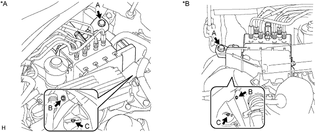
Text in Illustration *A for LHD *B for RHD Note
-
Do not damage the brake lines or wire harness.
-
Do not hold the actuator by the connector.
-
If the actuator is dropped, replace it.
-
Temporarily install each brake line to the correct positions of the brake actuator assembly as shown in the illustration.
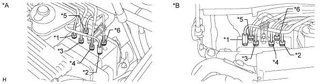
Text in Illustration *A for LHD *B for RHD Tech Tips
-
*1: to front wheel cylinder RH
-
*2: to front wheel cylinder LH
-
*3: to rear wheel cylinder RH
-
*4: to rear wheel cylinder LH
-
*5: from brake master cylinder
-
*6: from brake stroke simulator cylinder
-
-
Using a union nut wrench, tighten each brake line.
- Torque:
- Specified tightening torque
- 15 N*m { 155 kgf*cm, 11 ft.*lbf }
Tech Tips
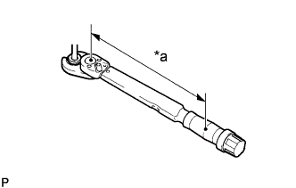
Text in Illustration *a Torque Wrench Fulcrum Length
-
Calculate the torque wrench reading when changing the fulcrum length of the torque wrench Click here.
-
When using a union nut wrench (fulcrum length of 22 mm (0.8661 in.)) + torque wrench (fulcrum length of 162 mm (6.3779 in.)): 13 N*m (137 kgf*cm, 10 ft.*lbf)
-
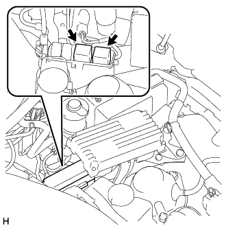
Connect the connector.
Note
-
Make sure that the connector is locked securely.
-
Make sure that the actuator connector can be connected smoothly. Do not allow water, oil or dirt to enter.
-
-
-
INSTALL SKID CONTROL ECU ASSEMBLY
-
CONNECT CABLE TO AUXILIARY BATTERY NEGATIVE TERMINAL
Note
When disconnecting the cable, some systems need to be initialized after the cable is reconnected Click here.
-
INSTALL LUGGAGE COMPARTMENT TRIM COVER LH
-
Install the luggage compartment trim cover LH.
-
-
INSTALL LUGGAGE COMPARTMENT FLOOR MAT
-
Install the luggage compartment floor mat.
-
-
BLEED BRAKE SYSTEM
CAUTION:
If the brake fluid is replaced without using the GTS, the procedure will be incomplete which could lead to problems or accidents. Always use the GTS when performing fluid replacement.
-
Bleed air from the brake system.
-
Remove the 2 ABS motor relays.
Tech Tips
If the ABS motor relays are already removed, this procedure is unnecessary.
-
With the power switch off, connect the GTS to the DLC3.
-
Remove the brake master cylinder reservoir filler cap assembly.
-
Adjust the brake fluid amount so that the brake fluid level is at the MIN level of the brake fluid reservoir.
-
Turn the power switch on (IG), turn the GTS on, and enter the following menus: Chassis / ABS/VSC/TRC / Utility / ECB (Electronically Controlled Brake system) Utility / Zero Down.
Tech Tips
Using the GTS to perform zero down causes the pressurized fluid in the accumulator to be returned to the brake fluid in the accumulator to be returned to the brake fluid reservoir.
-
Confirm the sounds of the buzzer and turn the power switch off.
-
Add brake fluid so that the fluid level is between the MIN and MAX lines of the brake fluid reservoir.
-
Turn the power switch on (IG), turn the GTS on, and enter the following menus: Chassis / ABS/VSC/TRC / Utility / ECB (Electronically Controlled Brake system) Invalid.
-
Bleed air from the No. 1 brake actuator tube.
Tech Tips
If the No. 1 brake actuator tube (between the master cylinder and brake actuator) is disconnected, bleed air using the following procedure.
-
Add brake fluid so that the fluid level is between the MIN and MAX lines of the brake fluid reservoir.
-
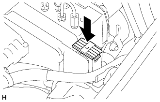
Remove the cover from the top of the brake master cylinder reservoir filler cap assembly.
-
Set the vacuum pump to pressurized state (discharge) and install the small diameter attachment to the hose.
-
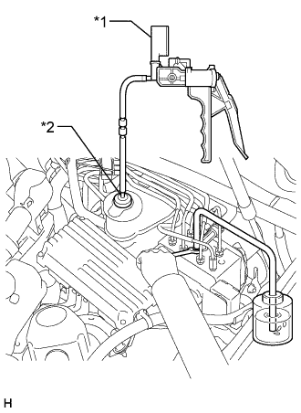
Insert the small diameter attachment into the air hole of the reservoir cap to install it.
Text in Illustration *1 Vacuum Pump *2 Small Diameter Attachment -
Connect a vinyl tube to the bleeder plug of the brake actuator.
-
Loosen the bleeder plug of the brake actuator.
-
Using the vacuum pump, increase the pressure inside the brake fluid reservoir.
-
Drain the air and brake fluid inside the tube and tighten the bleeder plug.
-
With the bleeder plug tightened, maintain the pressure in the brake fluid reservoir at 0.08 MPa, and then loosen the bleeder plug to bleed air.
NOTICE Perform this procedure 5 times or more. -
Tighten the bleeder plug all the air between the brake fluid reservoir and brake actuator is bled.
Torque 8.3 N*m (85 kgf*cm, 73 in.*lbf) -
Release the pressure in the brake fluid reservoir and remove the vinyl tube, vacuum pump and small diameter attachment.
-
Install the cover on the top of the brake master cylinder reservoir filler cap assembly.
-
-
Repeatedly depress the brake pedal to bleed the air from the bleeder plug of the front disc brake cylinder RH.
Tech Tips
Repeatedly depress the brake pedal 30 times or more, as air often remains inside the brake stroke simulator cylinder.
Note
Add fluid so that the fluid level does not drop below the MIN line on the brake fluid reservoir.
-
After bleeding the air, depress and hold the brake pedal, and tighten the bleeder plug.
- Torque:
- 11 N*m { 110 kgf*cm, 8 ft.*lbf }
-
In the same way as the RH side, bleed air from the bleeder plug of the front disc brake cylinder LH.
-
Follow the GTS screen, to end ECB (Electronically Controlled Brake system) Invalid.
-
Install the 2 ABS motor relays with the power switch off.
-
Turn the power switch on (IG), turn the GTS on, and enter the following menus: Chassis / ABS/VSC/TRC / Utility / ECB (Electronically Controlled Brake system) Utility / ECB (Electronically controlled Brake system) Invalid.
-
While depressing the brake pedal, loosen the bleeder plug of the rear disc brake cylinder LH. While the pump motor and solenoid are operating, bleed the air.
Note
Add fluid so that the fluid level does not drop below the MIN line on the brake fluid reservoir.
-
After bleeding the air, tighten the bleeder plug and release the brake pedal.
- Torque:
- 8.3 N*m { 85 kgf*cm, 73 in.*lbf }
-
In the same way as the LH side, bleed air from the bleeder plug of the rear disc brake cylinder RH.
-
Follow the GTS screen, to end ECB (Electronically Controlled Brake system) Invalid.
-
Adjust the brake fluid amount so that the brake fluid level is at the MIN level of the brake fluid reservoir.
-
Turn the power switch on (IG), turn the GTS on, and enter the following menus: Chassis / ABS/VSC/TRC / Utility / ECB (Electronically controlled Brake system) Utility / Zero Down.
-
Confirm the sounds of the buzzer and turn the power switch off.
-
Turn the power switch on (IG), and then after confirming that the pump motor stops operating, perform zero down again.
Tech Tips
The operation of the pump motor can be confirmed by listening to the operating sound.
-
In order to circulate the fluid inside the accumulator, perform "Zero Down" a total of 5 times.
-
-
Clear DTCs Click here.
-
Turn the GTS off and turn the power switch off.
-
Check for brake fluid leaks.
-
Inspect and adjust the brake fluid level in the reservoir Click here.
-
-
INSTALL ENGINE ROOM SIDE COVER LH
-
Attach the 2 clips to install the engine room side cover LH.
-
-
INSTALL FRONT WHEEL
- Torque:
- 103 N*m { 1050 kgf*cm, 76 ft.*lbf }
-
PERFORM INITIALIZATION AND CALIBRATION OF LINEAR SOLENOID VALVE (when Using the GTS)