BRAKE ACTUATOR REMOVAL

Tech Tips
-
Use the same procedure for the RHD and LHD vehicles.
-
The procedure listed below is for the LHD vehicles.
Note
While the battery is connected, even if the power switch is off, the brake control system activates when the brake pedal is depressed or the door courtesy switch turns on. Therefore during servicing of the brake system components, do not operate the brake pedal or open/close the doors while the battery is connected.
-
REMOVE FRONT WHEEL LH
-
REMOVE ENGINE ROOM SIDE COVER LH
-
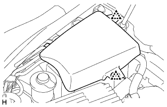
Detach the 2 clips and remove the engine room side cover LH.
-
-
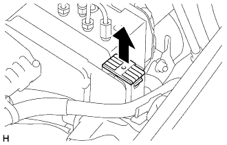
REMOVE ABS MOTOR RELAY
-
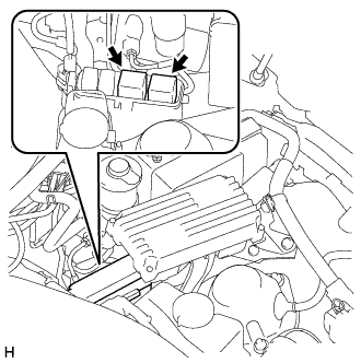
Remove the 2 ABS motor relays with the power switch off in order to disable brake control.
Tech Tips
This procedure is not required if the 2 ABS motor relays have been removed.
-
-
PERFORM ACCUMULATOR ZERO DOWN
-
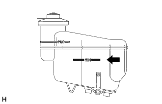
Drain the brake fluid in the reservoir near the MIN line.
-
Connect the GTS to the DLC3 with the power switch off.
-
Turn the power switch on (IG).
-
Turn the GTS on and enter the following menus: Chassis / ABS/VSC/TRC / Utility / ECB (Electronically controlled Brake system) Utility / Zero Down.
Tech Tips
Using the GTS to perform accumulator zero down causes the pressurized fluid in the accumulator to be returned to the brake fluid reservoir.
-
When the buzzer sounds, turn the power switch off.
-
Turn the GTS off.
-
-
DRAIN BRAKE FLUID
-
Drain the brake fluid until it reaches the MIN level.
Note
Wash off brake fluid immediately if it comes in contact with any painted surface.
-
-
PRECAUTION
Note
After turning the power switch off, waiting time may be required before disconnecting the cable from the auxiliary battery terminal. Therefore, make sure to read the disconnecting the cable from the auxiliary battery terminal notice before proceeding with work Click here.
-
REMOVE LUGGAGE COMPARTMENT FLOOR MAT
-
Remove the luggage compartment floor mat.
-
-
REMOVE LUGGAGE COMPARTMENT TRIM COVER LH
-
Remove the luggage compartment trim cover.
-
-
DISCONNECT CABLE FROM AUXILIARY BATTERY NEGATIVE TERMINAL
CAUTION:
Wait at least 90 seconds after disconnecting the cable from the auxiliary battery negative (-) terminal to disable the SRS system.
Note
When disconnecting the cable, some systems need to be initialized after the cable is reconnected Click here.
-
REMOVE SKID CONTROL ECU ASSEMBLY
-
REMOVE BRAKE ACTUATOR WITH BRACKET
-
Release the lock lever and disconnect the connector.
Note
Do not allow brake fluid to contact the connector face.
-
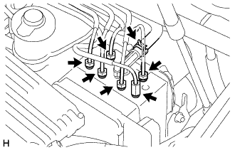
Using a union nut wrench, disconnect the 6 brake lines from the brake actuator assembly.
-
Move the hose clip and separate the No. 1 reservoir hose from the brake actuator assembly.
-
Use tags or make a mark to identify the places to reconnect.
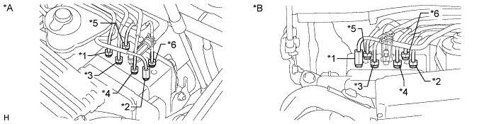
Text in Illustration *A for LHD *B for RHD Tech Tips
-
*1: to front wheel cylinder RH
-
*2: to front wheel cylinder LH
-
*3: to rear wheel cylinder RH
-
*4: to rear wheel cylinder LH
-
*5: from brake master cylinder
-
*6: from brake stroke simulator cylinder
-
-
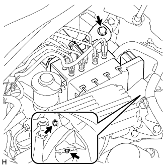
remove the 2 bolts, nut and actuator assembly with bracket from the body.
Note
Do not damage the brake tubes.
-
-
REMOVE NO. 5 BRAKE ACTUATOR BRACKET
-
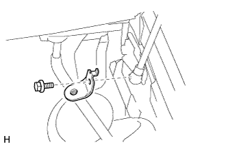
Remove the bolt and No. 5 brake actuator bracket from the body.
-