ELECTRONICALLY CONTROLLED BRAKE SYSTEM Brake Hold Standby Indicator Light Circuit
DESCRIPTION
-
When the brake hold switch is turned ON while the power switch is on (IG), if the brake hold operation is possible, the brake hold standby indicator light illuminates in green.
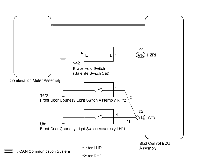
WIRING DIAGRAM
INSPECTION PROCEDURE
Note
When replacing the skid control ECU assembly, perform initialization and calibration of the linear solenoid valve Click here.
PROCEDURE
-
PRE-CHECK
-
If the brake hold standby indicator light does not illuminate even though the brake hold switch (satellite switch set) is pushed, check that the brake hold function operation conditions are met.
-
The driver's door is closed.
-
Driver's seat belt is fastened.
-
The engine hood is closed.
-
The trunk is closed.
-
The system is normal.
Tech Tips
If a malfunction occurs in one of the following systems, the brake hold operated indicator light will blink. If this occurs, perform troubleshooting on the malfunctioning system.
-
Electronically controlled brake system
-
ABS system
-
VSC system
-
Electric parking brake system
-
Hybrid control system
-
-
NEXT 
-
-
CHECK CAN COMMUNICATION SYSTEM
-
Check if a CAN communication system DTC is output (for LHD: Click here, for RHD: Click here.
Result Result Proceed to DTC is not output A DTC is output (for LHD) B DTC is output (for RHD) C
B 
INSPECT CAN COMMUNICATION SYSTEM Click here
C
INSPECT CAN COMMUNICATION SYSTEM Click here
A
-
-
INSPECT COMBINATION METER ASSEMBLY
-
Perform the Active Test of the combination meter assembly (meter CPU) using the GTS Click here.
-
Check the combination meter assembly.
OK The brake hold standby indicator light turns on or off in accordance with the GTS operation. Tech Tips
If troubleshooting has been carried out according to Problem Symptoms Table refer back to the table and proceed to the next step before replacing the part Click here.
NG
REPLACE COMBINATION METER ASSEMBLY Click here
OK
-
-
PERFORM ACTIVE TEST USING GTS (BRAKE HOLD STANDBY INDICATOR LIGHT)
-
Connect the GTS to the DLC3.
-
Turn the power switch on (IG).
-
Select the Active Test mode on the GTS.
ABS/VSC/TRC Tester Display Test Part Control Range Diagnostic Note BH Standby Light Brake hold standby indicator light Indicator light ON/OFF Observe combination meter -
Check that the brake hold standby indicator light on the combination meter assembly turns on or off in accordance with the GTS operation.
OK The brake hold standby indicator light turns on or off in accordance with the GTS operation.
NG
REPLACE SKID CONTROL ECU ASSEMBLY Click here
OK
-
-
INSPECT BRAKE HOLD SWITCH
-
Remove the brake hold switch (satellite switch set) Click here.
-
Inspect the brake hold switch (satellite switch set) Click here.
NG
REPLACE SATELLITE SWITCH SET Click here
OK
-
-
CHECK HARNESS AND CONNECTOR (SKID CONTROL ECU ASSEMBLY - BRAKE HOLD SWITCH)
-
Disconnect the A16 skid control ECU assembly connector.
-
Measure the resistance according to the value(s) in the table below.
Standard Resistance Tester Connection Condition Specified Condition A16-23 (HZRI) - N42-7 (+B) Always Below 1 Ω A16-23 (HZRI) - Body ground Always 10 kΩ or higher N42-4 (E) - Body ground Always Below 1 Ω
NG
REPAIR OR REPLACE HARNESS OR CONNECTOR (CTY CIRCUIT)
OK
-
-
INSPECT FRONT DOOR COURTESY LIGHT SWITCH ASSEMBLY
-
Turn on the interior lights and check that they illuminate, and then set the switch so that the lights illuminate when the door is opened.
-
Check that the lights illuminate when the driver door is opened.
OK The interior lights illuminate when the driver door is opened.
NG
INSPECT LIGHTING SYSTEM Click here
OK
-
-
CHECK HARNESS AND CONNECTOR (CTY TERMINAL)
-
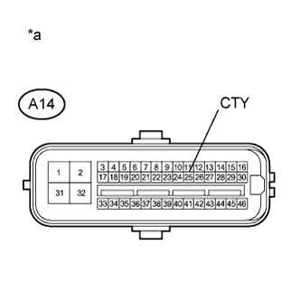
Disconnect the A14 skid control ECU assembly connector.
-
Measure the voltage and pulse according to the value(s) in the table below.
Standard Resistance Tester Connection Condition Specified Condition A14-25 (CTY) - Body ground Driver door open Below 1 V Driver door closed Pulse generation
NG
REPAIR OR REPLACE HARNESS OR CONNECTOR (CTY CIRCUIT)
OK 
REPLACE SKID CONTROL ECU ASSEMBLY Click here
-