FRONT SPEED SENSOR INSTALLATION

Tech Tips
-
Other than areas where instructions are provided, use the same procedures for the RH and LH sides.
-
The procedures listed below are for LH side.
-
INSTALL FRONT AXLE HUB SUB-ASSEMBLY (SKID CONTROL SENSOR)
-
INSPECT FRONT AXLE HUB BEARING LOOSENESS
-
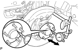
Using a dial indicator, check for looseness near the center of the axle hub.
Maximum 0.05 mm (0.0020 in.) Note
Ensure that the dial indicator is set at right angles to the measurement surface.
If looseness exceeds the maximum, replace the bearing.
-
-
INSPECT FRONT AXLE HUB RUNOUT
-
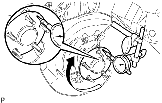
Using a dial indicator, check for runout on the surface of the axle hub outside the hub bolt.
Maximum 0.05 mm (0.0020 in.) Note
Ensure that the dial indicator is set at right angles to the measurement surface.
If runout exceeds the maximum, replace the axle hub.
-
-
INSTALL FRONT DISC
-
for 17 inch Front Disc Brake:
-
for 18 inch Front Disc Brake:
-
-
INSTALL DISC BRAKE CYLINDER ASSEMBLY LH
-
for 17 inch Front Disc Brake:
-
for 18 inch Front Disc Brake:
-
-
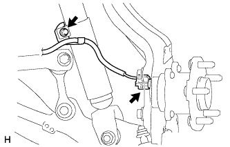
INSTALL SKID CONTROL SENSOR WIRE
-
Connect the connector.
Note
Securely connect the connector.
-
Install the 2 harness clamps with the 2 bolts.
- Torque:
- 6.0 N*m { 61 kgf*cm, 53 in.*lbf }
Note
-
Make sure the clamp rotation stopper touches the installation position.
-
When installing the clamps, do not twist the wire harness.
-
Attach the clip.
-
Install the front fender liner.
-
Install the harness clamp with the bolt.
- Torque:
- 6.0 N*m { 61 kgf*cm, 53 in.*lbf }
Note
When installing the clamps, do not twist the wire harness.
-
Connect the connector.
Note
Securely connect the connector.
-
-
INSTALL FRONT WHEEL
- Torque:
- 103 N*m { 1050 kgf*cm, 76 ft.*lbf }
-
INSPECT AND ADJUST FRONT WHEEL ALIGNMENT
-
INSPECT SPEED SENSOR SIGNAL