ELECTRONICALLY CONTROLLED BRAKE SYSTEM, Diagnostic DTC:C1377/43

| DTC Code | DTC Name |
|---|---|
| C1377/43 | Capacitor Malfunction |
DESCRIPTION
The brake control power supply assembly (capacitor) is used as auxiliary power for brake control when the auxiliary battery voltage is low.
| DTC Code | INF Code | DTC Detection Condition | Trouble Area |
|---|---|---|---|
| C1377/43 | 101 | Either of the following is detected:
|
Brake control power supply assembly |
| ↑ | 102 | Either of the following is detected:
|
↑ |
| ↑ | 103 | Either of the following is detected:
|
Apply high voltage |
| ↑ | 105 | Either of the following is detected:
|
Brake control power supply assembly |
| ↑ | 106 | Either of the following is detected:
|
↑ |
| ↑ | 108 | Either of the following is detected:
|
↑ |
| ↑ | 109 | Either of the following is detected:
|
|
| ↑ | 110 | Either of the following is detected:
|
Brake control power supply circuit |
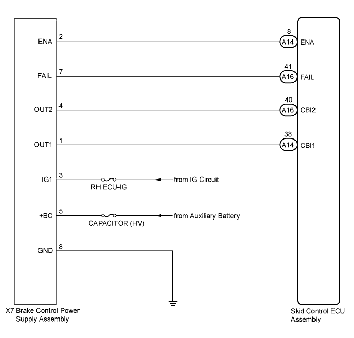
WIRING DIAGRAM
INSPECTION PROCEDURE
Note
-
When replacing the skid control ECU assembly, perform initialization and calibration of the linear solenoid valve Click here.
-
Inspect the fuses for circuits related to this system before performing the following inspection procedure.
PROCEDURE
-
CHECK FREEZE FRAME DATA
-
Check the INF code from the Freeze Frame Data memorized when the DTC (C1377/43) is stored Click here.
Result Result Proceed to INF codes (109 and/or 110) are output A INF codes (101, 102, 105, 106 and/or 108) are output B INF code (103) is output C
B 
REPLACE BRAKE CONTROL POWER SUPPLY ASSEMBLY Click here
C 
CHECK AUXILIARY BATTERY Click here
A 
-
-
CHECK HARNESS AND CONNECTOR (+BC TERMINAL)
-
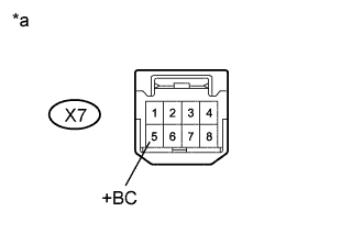
Text in Illustration *a Front view of wire harness connector
(to Brake Control Power Supply Assembly)
Make sure that there is no looseness at the locking part and the connecting part of the connector.
-
Disconnect the brake control power supply assembly connector.
-
Measure the voltage according to the value(s) in the table below.
Standard Voltage Tester Connection Condition Specified Condition X7-5 (+BC) - Body ground Always 11 to 14 V
NG
REPAIR OR REPLACE HARNESS OR CONNECTOR (+BC CIRCUIT)
OK
-
-
CHECK HARNESS AND CONNECTOR (GND TERMINAL)
-
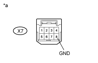
Text in Illustration *a Front view of wire harness connector
(to Brake Control Power Supply Assembly)
Measure the resistance according to the value(s) in the table below.
Standard Resistance Tester Connection Condition Specified Condition X7-8 (GND) - Body ground Always Below 1 Ω
NG
REPAIR OR REPLACE HARNESS OR CONNECTOR (GND CIRCUIT)
OK
-
-
INSPECT BRAKE CONTROL POWER SUPPLY ASSEMBLY (BRAKE CONTROL POWER SUPPLY ASSEMBLY POWER SUPPLY OUTPUT)
-
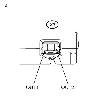
Text in Illustration *a Component with harness connected
(Brake Control Power Supply Assembly)
Reconnect the brake control power supply assembly connector.
-
Turn the power switch on (IG).
-
Measure the voltage according to the value(s) in the table below.
Standard Voltage Tester Connection Switch Condition Specified Condition X7-1 (OUT1) - Body ground Power switch on (IG) 11 to 14 V X7-4 (OUT2) - Body ground Power switch on (IG) 11 to 14 V
NG
REPLACE BRAKE CONTROL POWER SUPPLY ASSEMBLY Click here
OK
-
-
CHECK HARNESS AND CONNECTOR (SKID CONTROL ECU ASSEMBLY - BRAKE CONTROL POWER SUPPLY ASSEMBLY)
-
Turn the power switch on (IG).
-
Make sure that there is no looseness at the locking part and the connecting part of the connectors.
-
Disconnect the A14 and A16 skid control ECU assembly connectors and the X7 brake control power supply assembly connector.
-
Measure the resistance according to the value(s) in the table below.
Standard Resistance Tester Connection Condition Specified Condition A14-38 (CBI1) - X7-1 (OUT1) Always Below 1 Ω A14-38 (CBI1) - Body ground Always 10 kΩ or higher A16-40 (CBI2) - X7-4 (OUT2) Always Below 1 Ω A16-40 (CBI2) - Body ground Always 10 kΩ or higher
NG
REPAIR OR REPLACE HARNESS OR CONNECTOR
OK
-
-
RECONFIRM DTC
-
Reconnect the skid control ECU assembly connectors and the brake control power supply assembly connector.
-
Clear the DTCs Click here.
-
Turn the power switch on (IG).
-
Check if the same DTC is recorded Click here.
Result Result Proceed to DTC (C1377/43) is not output A DTC (C1377/43) is output B
B
REPLACE SKID CONTROL ECU ASSEMBLY Click here
A 
CHECK FOR INTERMITTENT PROBLEMS Click here
-
-
CHECK AUXILIARY BATTERY
-
Check the auxiliary battery voltage.
Standard Voltage Tester Connection Switch Condition Specified Condition Auxiliary battery Power switch on (IG) 11 to 14 V Auxiliary battery Power switch on (READY) 11 to 15.5 V
NG
CHARGE OR REPLACE AUXILIARY BATTERY
OK
-
-
CHECK HARNESS AND CONNECTOR (+BC TERMINAL)
-
Text in Illustration *a Front view of wire harness connector
(to Brake Control Power Supply Assembly)
Make sure that there is no looseness at the locking part and the connecting part of the connector.
-
Disconnect the brake control power supply assembly connector.
-
Measure the voltage according to the value(s) in the table below.
Standard Voltage Tester Connection Condition Specified Condition X7-5 (+BC) - Body ground Always 11 to 14 V
NG
REPAIR OR REPLACE HARNESS OR CONNECTOR (+BC CIRCUIT)
OK
-
-
CHECK HARNESS AND CONNECTOR (GND TERMINAL)
-
Text in Illustration *a Front view of wire harness connector
(to Brake Control Power Supply Assembly)
Measure the resistance according to the value(s) in the table below.
Standard Resistance Tester Connection Condition Specified Condition X7-8 (GND) - Body ground Always Below 1 Ω
NG
REPAIR OR REPLACE HARNESS OR CONNECTOR (GND CIRCUIT)
OK
REPLACE BRAKE CONTROL POWER SUPPLY ASSEMBLY Click here
-