ELECTRONICALLY CONTROLLED BRAKE SYSTEM, Diagnostic DTC:C1271/71, C1272/72, C1464/31, C1465/32

| DTC Code | DTC Name |
|---|---|
| C1271/71 | Low Output Signal of Front Speed Sensor RH (Test Mode DTC) |
| C1272/72 | Low Output Signal of Front Speed Sensor LH (Test Mode DTC) |
| C1464/31 | Front Speed Sensor RH Circuit |
| C1465/32 | Front Speed Sensor LH Circuit |
DESCRIPTION
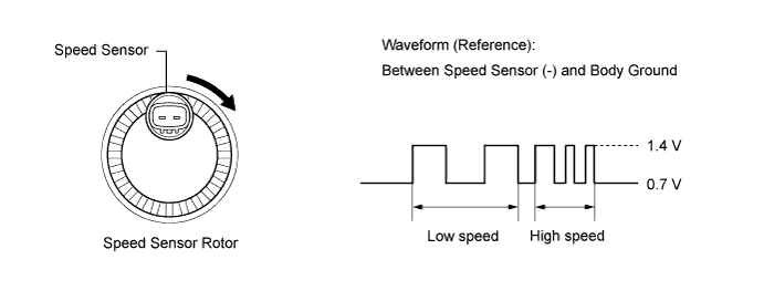
The speed sensor detects wheel speed and sends the appropriate signals to the skid control ECU assembly. These signals are used for ABS control.
DTCs C1271/71 and C1272/72 can be cleared when the speed sensor sends a wheel speed signal or when Test Mode ends. DTCs C1271/71 and C1272/72 are output only in Test Mode.
Tech Tips
The output voltage values shown below are those when the skid control ECU assembly and the speed sensors are connected to the vehicle harness.
| DTC Code | INF Code | DTC Detection Condition | Trouble Area |
|---|---|---|---|
| C1464/31 | 251 | At a vehicle speed of 10 km/h (6 mph) or more, an open or short in the sensor signal circuit of the abnormal wheel continues for 1 second or more. |
|
| ↑ | 252 | More than one speed sensor circuit signal is abnormal. | ↑ |
| ↑ | 253 | Speed sensor circuit signal is open for 0.5 seconds or more. | ↑ |
| ↑ | 254 | A momentary interruption of the sensor signal from the speed sensor occurs 255 times or more. | ↑ |
| ↑ | 255 | Frequency of 2.5 kHz or more is input. |
|
| ↑ | 262 | Either of the following is detected:
|
|
| C1465/32 | 264 | At a vehicle speed of 10 km/h (6 mph) or more, an open or short in the sensor signal circuit of the abnormal wheel continues for 1 second or more. |
|
| ↑ | 265 | More than one speed sensor circuit signal is abnormal. | ↑ |
| ↑ | 266 | Speed sensor circuit signal is open for 0.5 seconds or more. | ↑ |
| ↑ | 267 | A momentary interruption of the sensor signal from the speed sensor occurs 255 times or more. | ↑ |
| ↑ | 268 | Frequency of 2.5 kHz or more is input. |
|
| ↑ | 275 | Either of the following is detected:
|
|
| C1271/71 C1272/72 |
- | Detected only during Test Mode. |
|
Tech Tips
-
DTCs C1464/31 and C1271/71 are for the front speed sensor RH.
-
DTCs C1465/32 and C1272/72 are for the front speed sensor LH.
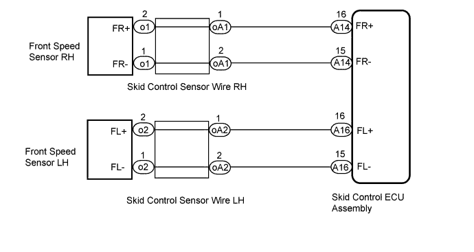
WIRING DIAGRAM
INSPECTION PROCEDURE
Note
When replacing the skid control ECU assembly, perform initialization and calibration of the linear solenoid valve Click here.
PROCEDURE
-
CHECK HARNESS AND CONNECTOR (MOMENTARY INTERRUPTION)
-
Using the GTS, check for any momentary interruptions in the wire harness and connector corresponding to a DTC Click here.
ABS/VSC/TRC Tester Display Measurement Item/Range Normal Condition Diagnostic Note FR Speed Open Front speed sensor RH open detection / Error or Normal Error: Momentary interruption
Normal: Normal
- FL Speed Open Front speed sensor LH open detection / Error or Normal Error: Momentary interruption
Normal: Normal
- OK There are no momentary interruptions. Tech Tips
Perform the above inspection before removing the sensor and connector.
NG 
REPAIR OR REPLACE HARNESS OR CONNECTOR
OK 
-
-
READ VALUE USING GTS (FRONT SPEED SENSOR)
-
Select the Data List on the GTS Click here.
ABS/VSC/TRC Tester Display Measurement Item/Range Normal Condition Diagnostic Note FR Wheel Speed Front wheel speed sensor RH / Min.: 0 km/h (0 mph), Max.: 326 km/h (202 mph) Vehicle stopped: 0 km/h (0 mph) When driving at constant speed: No large fluctuations FL Wheel Speed Front wheel speed sensor LH / Min.: 0 km/h (0 mph), Max.: 326 km/h (202 mph) Vehicle stopped: 0 km/h (0 mph) When driving at constant speed: No large fluctuations -
Check the speed value output from the speed sensor displayed on the GTS.
Tech Tips
Factors that affect the indicated vehicle speed include tire size, tire inflation, and tire wear. The speed indicated on the speedometer has an allowable margin of error. This can be tested using a speedometer tester (calibrated chassis dynamometer). For details about testing and the margin of error, see the reference chart Click here.
OK The speed value output from the speed sensor displayed on the GTS is similar to the speed indicated on the speedometer.
NG 
CHECK FRONT SPEED SENSOR INSTALLATION Click here
OK
-
-
PERFORM TEST MODE INSPECTION (SIGNAL CHECK)
-
Turn the power switch off.
-
Perform the sensor check in the Test Mode procedure Click here.
OK All Test Mode DTCs are cleared.
NG
CHECK FRONT SPEED SENSOR INSTALLATION Click here
OK
-
-
RECONFIRM DTC
-
Turn the power switch off.
-
Clear the DTCs Click here.
-
Turn the power switch on (READY).
-
Drive the vehicle at a speed of 10 km/h (6 mph) or more for at least 60 seconds.
-
Check if the same DTC is output Click here.
Result Result Proceed to DTCs (C1464/31 and C1465/32) are not output A DTCs (C1464/31 and/or C1465/32) are output B Tech Tips
If troubleshooting has been carried out according to Problem Symptoms Table, refer back to the table and proceed to the next step Click here.
B
REPLACE FRONT SPEED SENSOR AND FRONT SPEED SENSOR ROTOR Click here
A 
CHECK FOR INTERMITTENT PROBLEMS Click here
-
-
CHECK FRONT SPEED SENSOR INSTALLATION
-
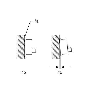
Text in Illustration *a No clearance *b OK *c NG Turn the power switch off.
-
Check the speed sensor installation.
OK There is no clearance between the sensor and the front axle hub.
NG
INSTALL FRONT SPEED SENSOR CORRECTLY Click here
OK
-
-
CHECK HARNESS AND CONNECTOR (SKID CONTROL SENSOR WIRE)
-
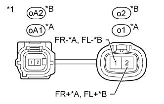
Text in Illustration *A for RH *B for LH *1 Skid Control Sensor Wire Make sure that there is no looseness at the locking part and the connecting part of the connectors.
-
Disconnect the skid control sensor wire connectors.
-
Measure the resistance according to the value(s) in the table below.
Standard Resistance for RH Tester Connection Condition Specified Condition o1-1 (FR-) - oA1-2 Always Below 1 Ω o1-2 (FR+) - oA1-1 Always Below 1 Ω o1-1 (FR-) - o1-2 (FR+) Always 10 kΩ or higher o1-1 (FR-) - Body ground Always 10 kΩ or higher o1-2 (FR+) - Body ground Always 10 kΩ or higher for LH Tester Connection Condition Specified Condition o2-1 (FL-) - oA2-2 Always Below 1 Ω o2-2 (FL+) - oA2-1 Always Below 1 Ω o2-1 (FL-) - o2-2 (FL+) Always 10 kΩ or higher o2-1 (FL-) - Body ground Always 10 kΩ or higher o2-2 (FL+) - Body ground Always 10 kΩ or higher Note
Check the speed sensor signal after replacement Click here.
NG
REPLACE SKID CONTROL SENSOR WIRE Click here
OK
-
-
CHECK HARNESS AND CONNECTOR (SKID CONTROL ECU ASSEMBLY - FRONT SPEED SENSOR)
-
Reconnect the oA1 or oA2 skid control sensor wire connector.
-
Make sure that there is no looseness at the locking part and the connecting part of the connector.
-
Disconnect the A14 or A16 skid control ECU assembly connector.
-
Measure the resistance according to the value(s) in the table below.
Standard Resistance for RH Tester Connection Condition Specified Condition A14-16 (FR+) - o1-2 (FR+) Always Below 1 Ω A14-16 (FR+) -Body ground Always 10 kΩ or higher A14-15 (FR-) - o1-1 (FR-) Always Below 1 Ω A14-15 (FR-) - Body ground Always 10 kΩ or higher for LH Tester Connection Condition Specified Condition A16-16 (FL+) - o2-2 (FL+) Always Below 1 Ω A16-16 (FL+) - Body ground Always 10 kΩ or higher A16-15 (FL-) - o2-1 (FL-) Always Below 1 Ω A16-15 (FL-) - Body ground Always 10 kΩ or higher
NG
REPAIR OR REPLACE HARNESS OR CONNECTOR
OK
-
-
INSPECT SKID CONTROL ECU ASSEMBLY (SENSOR OUTPUT)
-
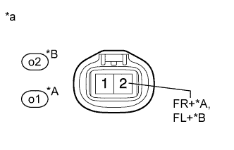
Text in Illustration *A for RH *B for LH *a Front view of skid control sensor wire
(to Front Speed Sensor)
Reconnect the skid control ECU assembly connector.
-
Turn the power switch on (IG).
-
Measure the voltage according to the value(s) in the table below.
Standard Voltage for RH Tester Connection Switch Condition Specified Condition o1-2 (FR+) - Body ground Power switch on (IG) 6.7 to 14 V for LH Tester Connection Switch Condition Specified Condition o2-2 (FL+) - Body ground Power switch on (IG) 6.7 to 14 V
NG
REPLACE SKID CONTROL ECU ASSEMBLY Click here
OK
-
-
RECONFIRM DTC
-
Turn the power switch off.
-
Reconnect the front speed sensor connector.
-
Clear the DTCs Click here.
-
Turn the power switch on (READY).
-
Drive the vehicle at a speed of 10 km/h (6 mph) or more for at least 60 seconds.
-
Check if the same DTC is output Click here.
Result Result Proceed to DTCs (C1464/31 and/or C1465/32) are output A DTCs (C1464/31 and C1465/32) are not output B Tech Tips
If troubleshooting has been carried out according to Problem Symptoms Table, refer back to the table and proceed to the next step Click here.
B
CHECK FOR INTERMITTENT PROBLEMS Click here
A
-
-
REPLACE FRONT SPEED SENSOR AND FRONT SPEED SENSOR ROTOR
-
Turn the power switch off.
-
Replace the front speed sensor and the front axle hub sub-assembly (front speed sensor rotor) Click here.
Tech Tips
The front speed sensor rotor is incorporated into the front axle hub.
If the front speed sensor rotor needs to be replaced, replace the front axle hub sub-assembly with front speed sensor.
Note
Check the speed sensor signal after replacement Click here.
NEXT
-
-
RECONFIRM DTC
-
Clear the DTCs Click here.
-
Turn the power switch on (READY).
-
Drive the vehicle at a speed of 10 km/h (6 mph) or more for at least 60 seconds.
-
Check if the same DTC is output Click here.
Result Result Proceed to DTCs (C1464/31 and/or C1465/32) are output A DTCs (C1464/31 and C1465/32) are not output B
B
END
A
REPLACE SKID CONTROL ECU ASSEMBLY Click here
-