TIRE PRESSURE WARNING SYSTEM, Diagnostic DTC:C2154/54

| DTC Code | DTC Name |
|---|---|
| C2154/54 | Initiator Driver Circuit (Open) |
DESCRIPTION
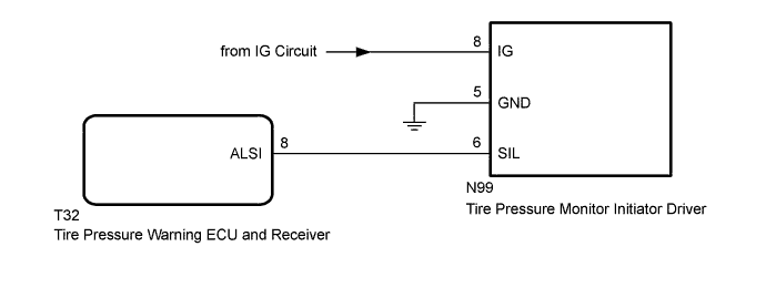
The tire pressure warning ECU and receiver and the tire pressure monitor initiator driver communicate via a direct communication line. When an open circuit between the tire pressure warning ECU and receiver and the tire pressure monitor initiator driver is detected, DTC C2154/54 is stored.
| DTC No. | DTC Detection Condition | Trouble Area |
|---|---|---|
| C2154/54 | When there is an open circuit between the tire pressure monitor initiator driver and the tire pressure warning ECU and receiver, the vehicle is driven at a speed of 8 km/h (5 mph) or more for a total of 30 seconds. |
|
WIRING DIAGRAM
INSPECTION PROCEDURE
Note
-
When replacing the tire pressure warning ECU and receiver, read the transmitter IDs stored in the old ECU using the GTS and write them down before removal.
-
It is necessary to perform initialization Click here after registration Click here of the transmitter IDs into the tire pressure warning ECU and receiver if the ECU has been replaced.
PROCEDURE
-
CHECK HARNESS AND CONNECTOR (TIRE PRESSURE MONITOR INITIATOR DRIVER IG VOLTAGE)
-
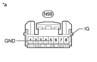
Text in Illustration *a Front view of wire harness connector
(to Tire Pressure Monitor Initiator Driver)
Turn the power switch off.
-
Disconnect the tire pressure monitor initiator driver connector.
-
Measure the voltage and resistance according to the value(s) in the table below.
Standard Voltage Tester Connection Switch Condition Specified Condition N99-8 (IG) - Body ground Power switch on (IG) 10 to 16 V Standard Resistance Tester Connection Condition Specified Condition N99-5 (GND) - Body ground Always Below 1 Ω
NG 
REPAIR OR REPLACE HARNESS OR CONNECTOR
OK 
-
-
CHECK HARNESS AND CONNECTOR (TIRE PRESSURE MONITOR INITIATOR DRIVER - TIRE PRESSURE WARNING ECU AND RECEIVER)
-
Turn the power switch off.
-
Disconnect the tire pressure monitor initiator driver N99 connector.
-
Disconnect the tire pressure warning ECU and receiver T32 connector.
-
Measure the resistance according to the value(s) in the table below.
Standard Resistance Tester Connection Condition Specified Condition N99-6 (SIL) - T32-8 (ALSI) Always Below 1 Ω N99-6 (SIL) - Body ground Always 10 kΩ or higher
NG
REPAIR OR REPLACE HARNESS OR CONNECTOR
OK
-
-
CHECK WAVEFORM
-
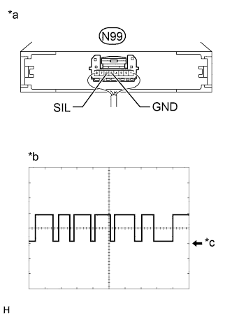
Text in Illustration *a Component with harness connected
(Tire Pressure Monitor Initiator Driver)
*b Example *c GND Connect the tire pressure monitor initiator driver connector.
-
Using an oscilloscope, check the waveform.
Waveform Item Contents Terminal N99-6 (SIL) - N99-5 (GND) Tool setting 5 V/DIV, 5 ms./DIV. Vehicle condition Power switch on (IG) Tech Tips
The waveform in the illustration is only an example for reference. When the voltage alternates between a "high" voltage (the voltage range from 2.2 V below the IG power supply voltage to the IG power supply voltage) and a "low" voltage (the voltage range from 0 to 1.2 V), the tire pressure warning ECU and receiver can be considered to be normal.
OK Voltage alternates between "high" and "low" voltage. Result Result Proceed to OK (for LHD) A OK (for RHD) B NG C
B
REPLACE TIRE PRESSURE MONITOR INITIATOR DRIVER Click here
C
REPLACE TIRE PRESSURE WARNING ECU AND RECEIVER Click here
A 
REPLACE TIRE PRESSURE MONITOR INITIATOR DRIVER Click here
-