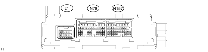
AIR CONDITIONING SYSTEM TERMINALS OF ECU

-
AIR CONDITIONING AMPLIFIER ASSEMBLY
-
Disconnect the N78 air conditioning amplifier assembly connector.
-
Measure the voltage and resistance according to the value(s) in the table below.
Terminal No. (Symbol) Wiring Color Terminal Description Condition Specified Condition N78-1 (GND) - Body ground W-B - Body ground Ground Always Below 1 Ω N78-5 (IG+) - N78-1 (GND) L - W-B Power source (IG) Power switch on (IG) 11 to 14 V N78-5 (IG+) - N78-1 (GND) L - W-B Power source (IG) Power switch off Below 1 V N78-6 (+B1) - N78-1 (GND) W - W-B Power source (+B) Always 11 to 14 V Tech Tips
If the result is not as specified, there may be a malfunction on the wire harness side.
-
Reconnect the N78 air conditioning amplifier assembly connector.
-
Measure the voltage, resistance and waveform according to the value(s) in the table below.
Tech Tips
Check from the rear of the connector while it is connected to the air conditioning amplifier assembly.
Terminal No. (Symbol) Wiring Color Terminal Description Condition Specified Condition N78-3 (BLW) - N78-1 (GND) W - W-B Blower motor speed control signal Power switch on (IG)
Blower switch: Lo
Pulse generation
(See waveform 1)
N78-8 (PTC1) - N78-1 (GND)*1 Y - W-B PTC heater relay operation signal Power switch on (Ready)
IDH signal terminal: Below 1 V
Combination switch: off
Set temperature: HI
Engine coolant temperature: 64°C (147.2°F) or lower
Ambient temperature: 10°C (50.0°F) or lower
Blower switch: off
11 to 14 V N78-8 (PTC1) - N78-1 (GND)*1 Y - W-B PTC heater relay operation signal Power switch on (Ready)
IDH signal terminal: Below 1 V
Combination switch: off
Set temperature: HI
Engine coolant temperature: 64°C (147.2°F) or lower
Ambient temperature: 10°C (50.0°F) or lower
Blower switch: Lo or more (after 10 seconds)
Below 1 V N78-9 (NANO) - N78-1 (GND)*2 R - W-B Ion generator operation signal Power switch on (IG)
Blower switch: Lo or more
Ion generator switch: off
11 to 14 V N78-9 (NANO) - N78-1 (GND)*2 R - W-B Ion generator operation signal Power switch on (IG)
Blower switch: Lo or more
Ion generator switch: on
Below 1 V N78-21 (RLIN) - N78-1 (GND)*6 P - W-B LIN communication signal Power switch on (IG) Pulse generation N78-22 (NAIN) - N78-1 (GND)*2 G - W-B Ion generator operation signal Power switch on (IG)
Blower switch: Lo or more
Ion generator switch: off
4.75 to 5.25 V N78-22 (NAIN) - N78-1 (GND)*2 G - W-B Ion generator operation signal Power switch on (IG)
Blower switch: Lo or more
Ion generator switch: on
Below 2.2 V N78-23 (IDH) - N78-1 (GND) W - W-B IDH signal Power switch on (Ready)
Quick heater assembly operation permitted
Below 1 V N78-23 (IDH) - N78-1 (GND) W - W-B IDH signal Power switch on (Ready)
Quick heater assembly operation not permitted
4.75 to 5.25 V N78-26 (PTC2) - N78-1 (GND)*1 B - W-B PTC heater relay operation signal Power switch on (Ready)
IDH signal terminal: Below 1 V
Combination switch: off
Set temperature: HI
Engine coolant temperature: 64°C (147.2°F) or lower
Ambient temperature: 10°C (50.0°F) or lower
Blower switch: off
11 to 14 V N78-26 (PTC2) - N78-1 (GND)*1 B - W-B PTC heater relay operation signal Power switch on (Ready)
IDH signal terminal: Below 1 V
Combination switch: off
Set temperature: HI
Engine coolant temperature: 64°C (147.2°F) or lower
Ambient temperature: 10°C (50.0°F) or lower
Blower switch: Lo or more (after 20 seconds)
Below 1 V N78-29 (ECOS) - N78-1 (GND) P - W-B Combination switch assembly operation signal Power switch on (IG)
Combination switch assembly not turned
11 to 14 V N78-29 (ECOS) - N78-1 (GND) P - W-B Combination switch assembly operation signal Power switch on (IG)
Combination switch assembly being turned and held at ECO position
Below 1 V N157-1 (SG-1) - Body ground G - Body ground Ground for room temperature sensor Always Below 1 Ω N157-3 (CANH) - N157-4 (CANL)*3 R - W CAN communication system CAN communication occurring Pulse generation N157-3 (CANH) - N157-4 (CANL)*4 Y - W CAN communication system CAN communication occurring Pulse generation N157-5 (S5-1) - N78-1 (GND) R - W-B Power supply for room humidity sensor, glass temperature sensor and glass surroundings temperature sensor Power switch on (IG) 4.75 to 5.25 V N157-7 (TSD) - N78-1 (GND)*3 SB - W-B Solar sensor signal (for Driver side) Power switch on (IG)
Solar sensor subjected to electric light
0.8 to 4.3 V N157-7 (TSD) - N78-1 (GND)*3 SB - W-B Solar sensor signal (for Driver side) Power switch on (IG)
Solar sensor covered with a cloth
Below 0.8 V N157-7 (TSD) - N78-1 (GND)*4 V - W-B Solar sensor signal (for Driver side) Power switch on (IG)
Solar sensor subjected to electric light
0.8 to 4.3 V N157-7 (TSD) - N78-1 (GND)*4 V - W-B Solar sensor signal (for Driver side) Power switch on (IG)
Solar sensor covered with a cloth
Below 0.8 V N157-8 (TSP) - N78-1 (GND)*3 V - W-B Solar sensor signal (for Front passenger side) Power switch on (IG)
Solar sensor subjected to electric light
0.8 to 4.3 V N157-8 (TSP) - N78-1 (GND)*3 V - W-B Solar sensor signal (for Front passenger side) Power switch on (IG)
Solar sensor covered with a cloth
Below 0.8 V N157-8 (TSP) - N78-1 (GND)*4 SB - W-B Solar sensor signal (for Front passenger side) Power switch on (IG)
Solar sensor subjected to electric light
0.8 to 4.3 V N157-8 (TSP) - N78-1 (GND)*4 SB - W-B Solar sensor signal (for Front passenger side) Power switch on (IG)
Solar sensor covered with a cloth
Below 0.8 V N157-9 (PRE) - N157-32 (SG-2) P - GR Air conditioning pressure sensor signal Power switch on (Ready)
Blower switch: Lo
A/C switch: on (magnet clutch on)
Refrigerant pressure: normal pressure (more than 0.19 MPa (2.0 kgf/cm2, 28 psi) to less than 3.14 MPa (32.0 kgf/cm2, 455 psi))
0.63 to 4.73 V N157-10 (TAM) - N157-32 (SG-2) V - GR Ambient temperature sensor signal Power switch on (IG)
Ambient temperature: 25°C (77°F)
1.35 to 1.75 V N157-13 (S5-3) - N157-32 (SG-2) LG - GR Power supply for flow sensor Power switch off Below 1 V N157-13 (S5-3) - N157-32 (SG-2) LG - GR Power supply for flow sensor Power switch on (IG) 4.75 to 5.25 V N157-16 (TR) - N157-1 (SG-1) P - G Room temperature sensor signal Power switch on (IG)
Cabin temperature: 25°C (77°F)
1.8 to 2.2 V N157-21 (TNG) - N157-33 (SG-5) GR - SB Glass surroundings temperature sensor signal Power switch on (IG)
Glass surroundings temperature: 25°C (77°F)
3.65 to 3.69 kΩ N157-22 (TFG) - N157-33 (SG-5) V - SB Glass temperature sensor signal Power switch on (IG)
Glass temperature: 25°C (77°F)
3.65 to 3.69 kΩ N157-23 (RH) - N157-33 (SG-5) Y - SB Room humidity sensor signal Power switch on (IG)
Cabin temperature: 25°C (77°F)
Glass humidity: 40%
2.09 V N157-23 (RH) - N157-33 (SG-5) Y - SB Room humidity sensor signal Power switch on (IG)
Cabin temperature: 25°C (77°F)
Glass humidity: 60%
2.81 V N157-24 (DGS) - N157-32 (SG-2)*5 R - GR Smog ventilation sensor signal (CO, HC) Power switch on (IG)
Cabin temperature: 20°C (68°F)
Glass humidity: 60%
Spray the clean air
15 to 40 kΩ N157-24 (DGS) - N157-32 (SG-2)*5 R - GR Smog ventilation sensor signal (CO, HC) Power switch on (IG)
Cabin temperature: 20°C (68°F)
Glass humidity: 40%
Spray the clean air
1.5 to 240 kΩ N157-25 (DGS1) - N157-32 (SG-2)*5 L - GR Smog ventilation sensor signal (NOx) Power switch on (IG)
Cabin temperature: 20°C (68°F)
Glass humidity: 65%
Spray the clean air
2.5 to 40 kΩ N157-32 (SG-2) - Body ground GR - Body ground Ground for air conditioning pressure sensor, ambient temperature sensor, flow sensor, compressor lock sensor and smog ventilation sensor*5 Always Below 1 Ω N157-33 (SG-5) - Body ground SB - Body ground Ground for room humidity sensor, glass temperature sensor and glass surroundings temperature sensor Always Below 1 Ω z1-1 (BUS G) - Body ground - Ground for BUS IC Always Below 1 Ω z1-2 (BUS) - z1-1 (BUS G) - BUS IC control signal Power switch on (IG) Pulse generation
(See waveform 2)
z1-3 (B BUS) - z1-1 (BUS G) - Power supply for BUS IC Always 11 to 14 V z1-12 (SGA) - Body ground - Ground for evaporator temperature sensor Always Below 1 V z1-11 (TEA) - z1-12 (SGA) - Evaporator temperature sensor signal Power switch on (IG)
Evaporator temperature: 0°C (32°F)
2.0 to 2.4 V z1-11 (TEA) - z1-12 (SGA) - Evaporator temperature sensor signal Power switch on (IG)
Evaporator temperature: 15°C (59°F)
1.4 to 1.8 V
-
*1: w/ PTC Heater
-
*2: w/ Ion Generator
-
*3: for LHD
-
*4: for RHD
-
*5: w/ Smog Ventilation Sensor
-
*6: w/ Rear Control Switch
-
-
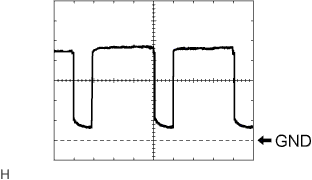
Waveform 1:
Item Content Terminal No. (Symbol) N78-3 (BLW) - N78-1 (GND) Tool Setting 1 V/DIV., 500 μs/DIV. Vehicle Condition Power switch on (IG)
Blower switch: Lo
-
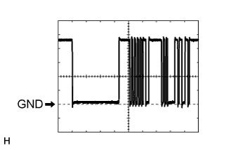
Waveform 2:
Item Content Terminal No. (Symbol) z1-2 (BUS) - z1-1 (BUS G) Tool Setting 1 V/DIV., 2 ms./DIV. Vehicle Condition Power switch on (IG)
-
-
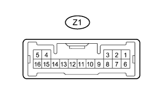
REAR CONTROL SWITCH (w/ Rear Control Switch)
-
Disconnect the Z1 rear control switch connector.
-
Measure the voltage and resistance according to the value(s) in the table below.
Terminal No. (Symbol) Wiring Color Terminal Description Condition Specified Condition Z1-1 (+B) - Z1-5 (E) R - W-B Power source (+B) Always 11 to 14 V Z1-7 (IG+) - Z1-5 (E) L - W-B Power source (IG) Power switch off Below 1 V Z1-7 (IG+) - Z1-5 (E) L - W-B Power source (IG) Power switch on (IG) 11 to 14 V Z1-5 (E) - Body ground W-B - Body ground Ground Always Below 1 Ω Tech Tips
If the result is not as specified, there may be a malfunction on the wire harness side.
-
Reconnect the Z1 rear control switch connector.
-
Measure the waveform according to the value(s) in the table below.
Tech Tips
Check from the rear of the connector while it is connected to the rear control switch.
Terminal No. (Symbol) Wiring Color Terminal Description Condition Specified Condition Z1-9 (RLIN) - Z1-5 (E) P - W-B LIN communication signal Power switch on (IG) Pulse generation
-
-
POWER MANAGEMENT CONTROL ECU
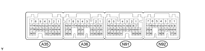
Power management control ECU Terminal No.
(Symbol)
Wiring Color Terminal Description Condition Specified Condition A35-1 (+B2) - N91-6 (E1) W - W-B Power source (+B) Power switch on (IG) 11 to 14 V A35-2 (WP) - N91-6 (E1) P - W-B Heater accessory assembly signal Power switch on (Ready)
Air conditioning system stopped
11 to 14 V A35-2 (WP) - N91-6 (E1) P - W-B Heater accessory assembly signal Power switch on (Ready)
Air conditioning system operated
0 to 2 V A36-1 (IG2) - N91-6 (E1) B - W-B Power source (IG) Power switch on (IG) 11 to 14 V A36-3 (+B1) - N91-6 (E1) W - W-B Power source (+B) Power switch on (IG) 11 to 14 V A36-16 (CLK) - N91-6 (E1) Y - W-B Air conditioning system communication signal Power switch on (Ready)
Air conditioning system stopped
Pulse generation
(See waveform 1)
A36-19 (STB) - N91-6 (E1) LG - W-B Air conditioning system communication signal Power switch on (Ready)
Air conditioning system stopped
Pulse generation
(See waveform 1)
A36-18 (ETI) - N91-6 (E1) V - W-B Air conditioning system communication signal Power switch on (Ready)
Air conditioning system stopped
Pulse generation
(See waveform 1)
A36-17 (ITE) - N91-6 (E1) W - W-B Air conditioning system communication signal Power switch on (Ready)
Air conditioning system stopped
Pulse generation
(See waveform 1)
N92-24 (CA1L) - N91-6 (E1) W - W-B CAN communication signal Power switch on (IG) Pulse generation
(See waveform 2)
N92-25 (CA1H) - N91-6 (E1) P - W-B CAN communication signal Power switch on (IG) Pulse generation
(See waveform 2)
-
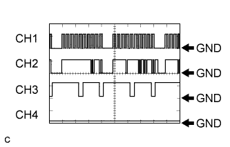
Waveform 1:
Item Content Terminal CH1: A36-16 (CLK) - N91-6 (E1)
CH2: A36-17 (ITE) - N91-6 (E1)
CH3: A36-18 (ETI) - N91-6 (E1)
CH4: A36-19 (STB) - N91-6 (E1)
Equipment Setting 10 V/DIV., 100 ms./DIV. Condition Power switch on (Ready)
Air conditioning system stopped
Tech Tips
The waveform will vary depending on the content of the digital communication (digital signal).
-
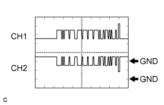
Waveform 2:
Item Content Terminal CH1: N92-25 (CA1H) - N91-6 (E1)
CH2: N92-24 (CA1L) - N91-6 (E1)
Equipment Setting 1 V/DIV., 50 μs./DIV. Condition Power switch on (IG) Tech Tips
The waveform will vary depending on the content of the digital communication (digital signal).
-