SEAT HEATER SYSTEM Seat Heater for Rear Left Seat does not Operate
DESCRIPTION
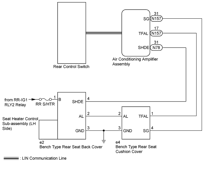
When the rear control switch is operated, the air conditioning amplifier assembly receives the signal. The rear control switch sends the signal to the air conditioning amplifier assembly through LIN communication. The air conditioning amplifier assembly receives the signal and operates the seat heater.
WIRING DIAGRAM
INSPECTION PROCEDURE
Note
-
Inspect the fuses and relays for circuits related to this system before performing the following inspection procedure.
-
If the auxiliary battery voltage becomes low, seat heater operation is canceled to prioritize supplying power to the power steering system.
Tech Tips
Since the seat heater system has functions that use LIN communication, first confirm that there is no malfunction in the communication system by inspecting the LIN communication functions in accordance with the "How to Proceed with Troubleshooting" procedures. Then, conduct the following inspection procedure.
PROCEDURE
-
CHECK FOR DTC
-
Check for DTCs Click here.
Result Result Proceed to DTC B14B3 and B14C3 is not output A DTC B14B3 is output B DTC B14C3 is output C
B 
GO TO DTC B14B3 Click here
C
GO TO DTC B14C3 Click here
A 
-
-
INSPECT BENCH TYPE REAR SEAT CUSHION COVER
-
Remove the bench type rear seat cushion cover Click here.
-
Inspect the bench type rear seat cushion cover Click here.
NG
REPLACE BENCH TYPE REAR SEAT CUSHION COVER Click here
OK
-
-
INSPECT BENCH TYPE REAR SEAT BACK COVER
-
Remove the bench type rear seat cushion cover Click here.
-
Inspect the bench type rear seat cushion cover Click here.
NG
REPLACE BENCH TYPE REAR SEAT BACK COVER Click here
OK
-
-
CHECK HARNESS AND CONNECTOR (BENCH TYPE REAR SEAT BACK COVER - BATTERY AND BODY GROUND)
-
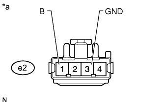
Text in Illustration *a Front view of wire harness connector
(to Bench Type Rear Seat Back Cover)
Disconnect the bench type rear seat back cover connector.
-
Measure the voltage and resistance according to the value(s) in the table below.
Standard Voltage Tester Connection Switch Condition Specified Condition e2-1 (B) - body ground Power switch on (IG) 11 to 14 V Standard Resistance Tester Connection Condition Specified Condition e2-3 (GND) - Body ground Always Below 1 Ω
NG
REPAIR OR REPLACE HARNESS OR CONNECTOR
OK
-
-
CHECK HARNESS AND CONNECTOR (AIR CONDITIONING AMPLIFIER ASSEMBLY - BENCH TYPE REAR SEAT BACK COVER)
-
Disconnect the N78 air conditioning amplifier assembly connector.
-
Disconnect the e2 bench type rear seat back cover connector.
-
Measure the resistance according to the value(s) in the table below.
Standard Resistance Tester Connection Condition Specified Condition N78-31 (SHDE) - e2-4 (SHDE) Always Below 1 Ω N78-31 (SHDE) - Body ground Always 10 kΩ or higher
NG
REPAIR OR REPLACE HARNESS OR CONNECTOR
OK
-
-
CHECK HARNESS AND CONNECTOR (AIR CONDITIONING AMPLIFIER ASSEMBLY - BENCH TYPE REAR SEAT CUSHION COVER)
-
Disconnect the N157 air conditioning amplifier assembly connector.
-
Disconnect the e4 bench type rear seat cushion cover connector.
-
Measure the resistance according to the value(s) in the table below.
Standard Resistance Tester Connection Condition Specified Condition N157-17 (TFAL) - e4-1 (TFAL) Always Below 1 Ω N157-31 (SG) - e4-4 (SG) Always Below 1 Ω N157-17 (TFAL) - Body ground Always 10 kΩ or higher N157-31 (SG) - Body ground Always 10 kΩ or higher
NG
REPAIR OR REPLACE HARNESS OR CONNECTOR
OK
-
-
CHECK HARNESS AND CONNECTOR (BENCH TYPE REAR SEAT CUSHION COVER - BENCH TYPE REAR SEAT BACK COVER AND BODY GROUND)
-
Disconnect the e4 bench type rear seat cushion cover connector.
-
Disconnect the e2 bench type rear seat back cover connector.
-
Measure the resistance according to the value(s) in the table below.
Standard Resistance Tester Connection Condition Specified Condition e4-2 (AL) - e2-2 (AL) Always Below 1 Ω e4-3 (GND) - e2-3 (GND) Always Below 1 Ω e4-2 (AL) - Body ground Always 10 kΩ or higher e4-3 (GND) - Body ground Always Below 1 Ω
NG
REPAIR OR REPLACE HARNESS OR CONNECTOR
OK
-
-
REPLACE SEAT HEATER CONTROL SUB-ASSEMBLY (LH SIDE)
-
Temporarily replace the seat heater control sub-assembly (LH side) with a new or normally functioning one Click here.
NEXT
-
-
CHECK SEAT HEATER SYSTEM
-
Check the seat heater system Click here.
OK Seat heater system operates normally
NG 
REPLACE REAR CONTROL SWITCH Click here
OK 
END (SEAT HEATER CONTROL SUB-ASSEMBLY [LH SIDE] WAS DEFECTIVE)
-
-
REPLACE REAR CONTROL SWITCH
-
Temporarily replace the rear control switch with a new or normally functioning one Click here.
NEXT
-
-
CHECK SEAT HEATER SYSTEM
-
Check the seat heater system Click here.
OK Seat heater system operates normally
NG
REPLACE AIR CONDITIONING AMPLIFIER ASSEMBLY Click here
OK
END (REAR CONTROL SWITCH WAS DEFECTIVE)
-