FRONT POWER SEAT CONTROL SYSTEM (for RHD), Diagnostic DTC:B2658

| DTC Code | DTC Name |
|---|---|
| B2658 | Short in Sensor with Motor Power Supply Circuit |
DESCRIPTION
This DTC is stored when a power seat motor operates (a position control sensor is being supplied with power) and the power supply voltage does not rise to the specified value.
| DTC Code | DTC Detection Condition | Trouble Area |
|---|---|---|
| B2658 | A problem with the voltage supplied to the position control sensor. |
|
-
*1: for Driver Side (Standard Seat Type)
-
*2: for Driver Side (Sports Seat Type)
-
*3: for Driver Side (Luxury Seat Type)
-
*4: for Front Passenger Side (Luxury Seat Type)
WIRING DIAGRAM
-
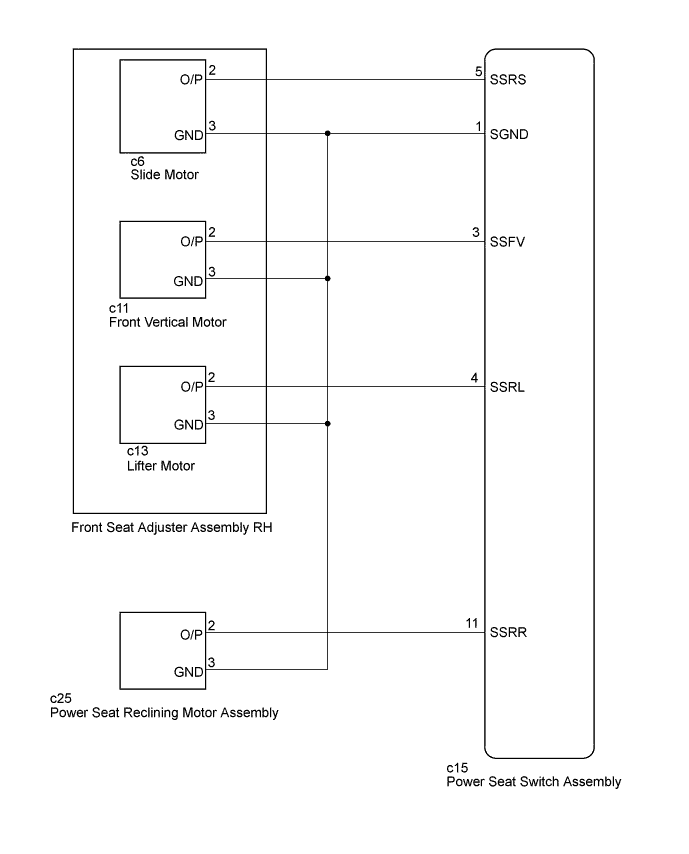
for Driver Side (Standard Seat Type):
-
for Driver Side (Sports Seat Type):
-
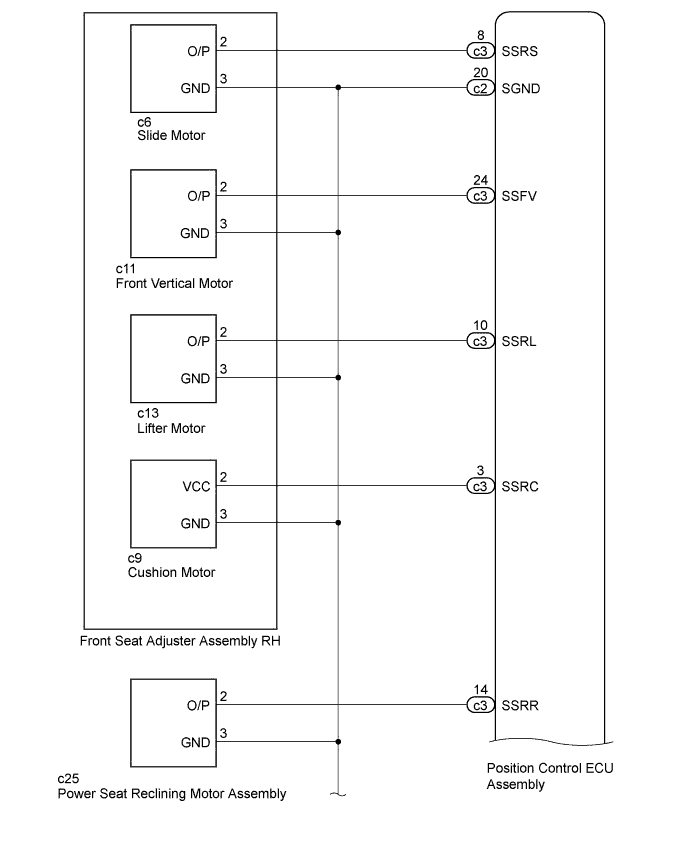
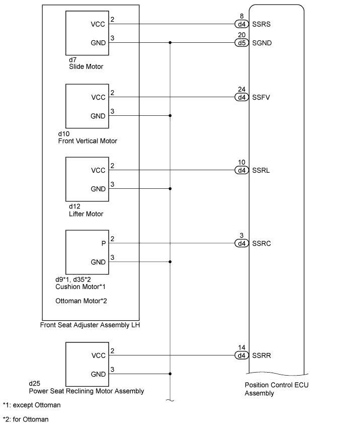
for Driver Side (Luxury Seat Type):
-
for Front Passenger Side (Luxury Seat Type):
INSPECTION PROCEDURE
PROCEDURE
-
CHECK FOR DTC
-
Clear the DTCs Click here.
-
Check for DTCs Click here.
Result Result Proceed to B2658 is output (for Driver Side, Standard Seat Type). A B2658 is output (for Driver Side, Sports Seat Type). B B2658 is output (for Driver Side, Luxury Seat Type). C B2658 is output (for Front Passenger Side, Luxury Seat Type). D B2658 is not output. E
B 
CHECK HARNESS AND CONNECTOR (POSITION CONTROL ECU ASSEMBLY - FRONT SEAT ADJUSTER ASSEMBLY RH) Click here
C
CHECK HARNESS AND CONNECTOR (POSITION CONTROL ECU ASSEMBLY - FRONT SEAT ADJUSTER ASSEMBLY RH) Click here
D
CHECK HARNESS AND CONNECTOR (POSITION CONTROL ECU ASSEMBLY - FRONT SEAT ADJUSTER ASSEMBLY LH) Click here
E 
USE SIMULATION METHOD TO CHECK Click here
A 
-
-
CHECK HARNESS AND CONNECTOR (POWER SEAT SWITCH ASSEMBLY - FRONT SEAT ADJUSTER ASSEMBLY RH)
-
Disconnect the c15 power seat switch assembly connector.
-
Disconnect the c6 slide motor connector.
-
Measure the resistance according to the value(s) in the table below.
Standard Resistance Tester Connection Condition Specified Condition c15-5 (SSRS) - c6-2 (O/P) Always Below 1 Ω c15-1 (SGND) - c6-3 (GND) Always Below 1 Ω c15-5 (SSRS) - c15-1 (SGND) Always 10 kΩ or higher c15-5 (SSRS) - Body ground Always 10 kΩ or higher c15-1 (SGND) - Body ground Always 10 kΩ or higher
NG
REPAIR OR REPLACE HARNESS OR CONNECTOR
OK
-
-
CHECK POWER SEAT SWITCH ASSEMBLY (SLIDE MOTOR CIRCUIT)
-

Text in Illustration *a Front view of wire harness connector
(to Front Seat Adjuster Assembly RH [Slide Motor])
Reconnect the c15 power seat switch assembly connector.
-
Measure the voltage according to the value(s) in the table below.
Standard Voltage Tester Connection Switch Condition Specified Condition c6-2 (O/P) - c6-3 (GND) Sliding switch on 4.8 to 5.1 V
NG
REPLACE POWER SEAT SWITCH ASSEMBLY Click here
OK
-
-
CHECK HARNESS AND CONNECTOR (POWER SEAT SWITCH ASSEMBLY - FRONT SEAT ADJUSTER ASSEMBLY RH)
-
Disconnect the c15 power seat switch assembly connector.
-
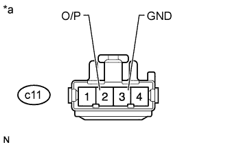
Disconnect the c11 front vertical motor connector.
-
Measure the resistance according to the value(s) in the table below.
Standard Resistance Tester Connection Condition Specified Condition c15-3 (SSFV) - c11-2 (O/P) Always Below 1 Ω c15-1 (SGND) - c11-3 (GND) Always Below 1 Ω c15-3 (SSFV) - c15-1 (SGND) Always 10 kΩ or higher c15-3 (SSFV) - Body ground Always 10 kΩ or higher c15-1 (SGND) - Body ground Always 10 kΩ or higher
NG
REPAIR OR REPLACE HARNESS OR CONNECTOR
OK
-
-
CHECK POWER SEAT SWITCH ASSEMBLY (FRONT VERTICAL MOTOR CIRCUIT)
-

Text in Illustration *a Front view of wire harness connector
(to Front Seat Adjuster Assembly RH [Front Vertical Motor])
Reconnect the c15 power seat switch assembly connector.
-
Measure the voltage according to the value(s) in the table below.
Standard Voltage Tester Connection Switch Condition Specified Condition c11-2 (O/P) - c11-3 (GND) Front vertical switch on 4.8 to 5.1 V
NG
REPLACE POWER SEAT SWITCH ASSEMBLY Click here
OK
-
-
CHECK HARNESS AND CONNECTOR (POWER SEAT SWITCH ASSEMBLY - FRONT SEAT ADJUSTER ASSEMBLY RH)
-
Disconnect the c15 power seat switch assembly connector.
-
Disconnect the c13 lifter motor connector.
-
Measure the resistance according to the value(s) in the table below.
Standard Resistance Tester Connection Condition Specified Condition c15-4 (SSRL) - c13-2 (O/P) Always Below 1 Ω c15-1 (SGND) - c13-3 (GND) Always Below 1 Ω c15-4 (SSRL) - c15-1 (SGND) Always 10 kΩ or higher c15-4 (SSRL) - Body ground Always 10 kΩ or higher c15-1 (SGND) - Body ground Always 10 kΩ or higher
NG
REPAIR OR REPLACE HARNESS OR CONNECTOR
OK
-
-
CHECK POWER SEAT SWITCH ASSEMBLY (LIFTER MOTOR CIRCUIT)
-

Text in Illustration *a Front view of wire harness connector
(to Front Seat Adjuster Assembly RH [Lifter Motor])
Reconnect the c15 power seat switch assembly connector.
-
Measure the voltage according to the value(s) in the table below.
Standard Voltage Tester Connection Switch Condition Specified Condition c13-2 (O/P) - c13-3 (GND) Lifter switch on 4.8 to 5.1 V
NG
REPLACE POWER SEAT SWITCH ASSEMBLY Click here
OK
-
-
CHECK FRONT SEAT ADJUSTER ASSEMBLY RH
-
Temporarily replace the front seat adjuster assembly RH with a new or normally functioning one Click here.
-
Clear the DTCs Click here.
-
Check for DTCs Click here.
OK DTC B2658 is not output.
NG
CHECK HARNESS AND CONNECTOR (POWER SEAT SWITCH ASSEMBLY - POWER SEAT RECLINING MOTOR ASSEMBLY) Click here
OK 
END (FRONT SEAT ADJUSTER ASSEMBLY RH WAS DEFECTIVE)
-
-
CHECK HARNESS AND CONNECTOR (POWER SEAT SWITCH ASSEMBLY - POWER SEAT RECLINING MOTOR ASSEMBLY)
-
Disconnect the c15 power seat switch assembly connector.
-
Disconnect the c25 reclining motor connector.
-
Measure the resistance according to the value(s) in the table below.
Standard Resistance Tester Connection Condition Specified Condition c15-11 (SSRR) - c25-2 (O/P) Always Below 1 Ω c15-1 (SGND) - c25-3 (GND) Always Below 1 Ω c15-11 (SSRR) - c15-1 (SGND) Always 10 kΩ or higher c15-11 (SSRR) - Body ground Always 10 kΩ or higher c15-1 (SGND) - Body ground Always 10 kΩ or higher
NG
REPAIR OR REPLACE HARNESS OR CONNECTOR
OK
-
-
CHECK POWER SEAT SWITCH ASSEMBLY (RECLINING MOTOR CIRCUIT)
-
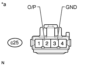
Text in Illustration *a Front view of wire harness connector
(to Power Seat Reclining Motor Assembly)
Reconnect the c15 power seat switch assembly connector.
-
Measure the voltage according to the value(s) in the table below.
Standard Voltage Tester Connection Switch Condition Specified Condition c25-2 (O/P) - c25-3 (GND) Reclining switch on 4.8 to 5.1 V
NG
REPLACE POWER SEAT SWITCH ASSEMBLY Click here
OK
-
-
CHECK POWER SEAT RECLINING MOTOR ASSEMBLY
-
Temporarily replace the power seat reclining motor assembly with a new or normally functioning one Click here.
-
Clear the DTCs Click here.
-
Check for DTCs Click here.
OK DTC B2658 is not output.
NG
REPLACE POWER SEAT SWITCH ASSEMBLY Click here
OK
END (POWER SEAT RECLINING MOTOR ASSEMBLY WAS DEFECTIVE)
-
-
CHECK HARNESS AND CONNECTOR (POSITION CONTROL ECU ASSEMBLY - FRONT SEAT ADJUSTER ASSEMBLY RH)
-
Disconnect the c2 and c3 position control ECU assembly connectors.
-
Disconnect the c6 slide motor connector.
-
Measure the resistance according to the value(s) in the table below.
Standard Resistance Tester Connection Condition Specified Condition c3-8 (SSRS) - c6-2 (O/P) Always Below 1 Ω c2-20 (SGND) - c6-3 (GND) Always Below 1 Ω c3-8 (SSRS) - c2-20 (SGND) Always 10 kΩ or higher c3-8 (SSRS) - Body ground Always 10 kΩ or higher c2-20 (SGND) - Body ground Always 10 kΩ or higher
NG
REPAIR OR REPLACE HARNESS OR CONNECTOR
OK
-
-
CHECK POSITION CONTROL ECU ASSEMBLY (SLIDE MOTOR CIRCUIT)
-

Text in Illustration *a Front view of wire harness connector
(to Front Seat Adjuster Assembly RH [Slide Motor])
Reconnect the c2 and c3 position control ECU assembly connectors.
-
Measure the voltage according to the value(s) in the table below.
Standard Voltage Tester Connection Switch Condition Specified Condition c6-2 (O/P) - c6-3 (GND) Sliding switch on 4.8 to 5.1 V
NG
REPLACE POSITION CONTROL ECU ASSEMBLY Click here
OK
-
-
CHECK HARNESS AND CONNECTOR (POSITION CONTROL ECU ASSEMBLY - FRONT SEAT ADJUSTER ASSEMBLY RH)
-
Disconnect the c2 and c3 position control ECU assembly connectors.
-
Disconnect the c11 front vertical motor connector.
-
Measure the resistance according to the value(s) in the table below.
Standard Resistance Tester Connection Condition Specified Condition c3-24 (SSFV) - c11-2 (O/P) Always Below 1 Ω c2-20 (SGND) - c11-3 (GND) Always Below 1 Ω c3-24 (SSFV) - c2-20 (SGND) Always 10 kΩ or higher c3-24 (SSFV) - Body ground Always 10 kΩ or higher c2-20 (SGND) - Body ground Always 10 kΩ or higher
NG
REPAIR OR REPLACE HARNESS OR CONNECTOR
OK
-
-
CHECK POSITION CONTROL ECU ASSEMBLY (FRONT VERTICAL MOTOR CIRCUIT)
-

Text in Illustration *a Front view of wire harness connector
(to Front Seat Adjuster Assembly RH [Front Vertical Motor])
Reconnect the c2 and c3 position control ECU assembly connectors.
-
Measure the voltage according to the value(s) in the table below.
Standard Voltage Tester Connection Switch Condition Specified Condition c11-2 (O/P) - c11-3 (GND) Front vertical switch on 4.8 to 5.1 V
NG
REPLACE POSITION CONTROL ECU ASSEMBLY Click here
OK
-
-
CHECK HARNESS AND CONNECTOR (POSITION CONTROL ECU ASSEMBLY - FRONT SEAT ADJUSTER ASSEMBLY RH)
-
Disconnect the c2 and c3 position control ECU assembly connectors.
-
Disconnect the c13 lifter motor connector.
-
Measure the resistance according to the value(s) in the table below.
Standard Resistance Tester Connection Condition Specified Condition c3-10 (SSRL) - c13-2 (O/P) Always Below 1 Ω c2-20 (SGND) - c13-3 (GND) Always Below 1 Ω c3-10 (SSRL) - c2-20 (SGND) Always 10 kΩ or higher c3-10 (SSRL) - Body ground Always 10 kΩ or higher c2-20 (SGND) - Body ground Always 10 kΩ or higher
NG
REPAIR OR REPLACE HARNESS OR CONNECTOR
OK
-
-
CHECK POSITION CONTROL ECU ASSEMBLY (LIFTER MOTOR CIRCUIT)
-

Text in Illustration *a Front view of wire harness connector
(to Front Seat Adjuster Assembly RH [Lifter Motor])
Reconnect the c2 and c3 position control ECU assembly connectors.
-
Measure the voltage according to the value(s) in the table below.
Standard Voltage Tester Connection Switch Condition Specified Condition c13-2 (O/P) - c13-3 (GND) Lifter switch on 4.8 to 5.1 V
NG
REPLACE POSITION CONTROL ECU ASSEMBLY Click here
OK
-
-
CHECK HARNESS AND CONNECTOR (POSITION CONTROL ECU ASSEMBLY - FRONT SEAT ADJUSTER ASSEMBLY RH)
-
Disconnect the c2 and c3 position control ECU assembly connectors.
-
Disconnect the c9 cushion motor connector.
-
Measure the resistance according to the value(s) in the table below.
Standard Resistance Tester Connection Condition Specified Condition c3-3 (SSRC) - c9-2 (VCC) Always Below 1 Ω c2-20 (SGND) - c9-3 (GND) Always Below 1 Ω c3-3 (SSRC) - c9-20 (SGND) Always 10 kΩ or higher c3-3 (SSRC) - Body ground Always 10 kΩ or higher c2-20 (SGND) - Body ground Always 10 kΩ or higher
NG
REPAIR OR REPLACE HARNESS OR CONNECTOR
OK
-
-
CHECK POSITION CONTROL ECU ASSEMBLY (CUSHION MOTOR CIRCUIT)
-

Text in Illustration *a Front view of wire harness connector
(to Front Seat Adjuster Assembly RH [Cushion Motor])
Reconnect the c2 and c3 position control ECU assembly connectors.
-
Measure the voltage according to the value(s) in the table below.
Standard Voltage Tester Connection Switch Condition Specified Condition c9-2 (VCC) - c9-3 (GND) Cushion switch on 4.8 to 5.1 V
NG
REPLACE POSITION CONTROL ECU ASSEMBLY Click here
OK
-
-
CHECK FRONT SEAT ADJUSTER ASSEMBLY RH
-
Temporarily replace the front seat adjuster assembly RH with a new or normally functioning one Click here.
-
Clear the DTCs Click here.
-
Check for DTCs Click here.
OK DTC B2658 is not output.
NG
CHECK HARNESS AND CONNECTOR (POSITION CONTROL ECU ASSEMBLY - POWER SEAT RECLINING MOTOR ASSEMBLY) Click here
OK
END (FRONT SEAT ADJUSTER ASSEMBLY RH WAS DEFECTIVE)
-
-
CHECK HARNESS AND CONNECTOR (POSITION CONTROL ECU ASSEMBLY - POWER SEAT RECLINING MOTOR ASSEMBLY)
-
Disconnect the c2 and c3 position control ECU assembly connectors.
-
Disconnect the c25 reclining motor connector.
-
Measure the resistance according to the value(s) in the table below.
Standard Resistance Tester Connection Condition Specified Condition c3-14 (SSRR) - c25-2 (O/P) Always Below 1 Ω c2-20 (SGND) - c25-3 (GND) Always Below 1 Ω c3-14 (SSRR) - c2-20 (SGND) Always 10 kΩ or higher c3-14 (SSRR) - Body ground Always 10 kΩ or higher c2-20 (SGND) - Body ground Always 10 kΩ or higher
NG
REPAIR OR REPLACE HARNESS OR CONNECTOR
OK
-
-
CHECK POSITION CONTROL ECU ASSEMBLY (RECLINING MOTOR CIRCUIT)
-
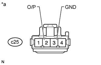
Text in Illustration *a Front view of wire harness connector
(to Power Seat Reclining Motor Assembly)
Reconnect the c2 and c3 position control ECU assembly connectors.
-
Measure the voltage according to the value(s) in the table below.
Standard Voltage Tester Connection Switch Condition Specified Condition c25-2 (O/P) - c25-3 (GND) Reclining switch on 4.8 to 5.1 V
NG
REPLACE POSITION CONTROL ECU ASSEMBLY Click here
OK
-
-
CHECK POWER SEAT RECLINING MOTOR ASSEMBLY
-
Temporarily replace the power seat reclining motor assembly with a new or normally functioning one Click here.
-
Clear the DTCs Click here.
-
Check for DTCs Click here.
OK DTC B2658 is not output.
NG
CHECK HARNESS AND CONNECTOR (POSITION CONTROL ECU ASSEMBLY - LUMBAR SUPPORT ADJUSTER ASSEMBLY RH) Click here
OK
END (POWER SEAT RECLINING MOTOR ASSEMBLY WAS DEFECTIVE)
-
-
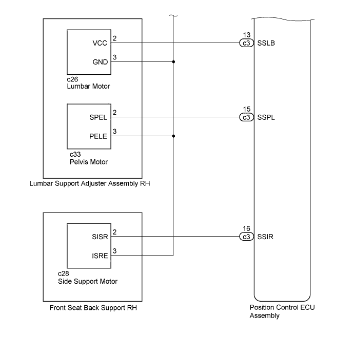
CHECK HARNESS AND CONNECTOR (POSITION CONTROL ECU ASSEMBLY - LUMBAR SUPPORT ADJUSTER ASSEMBLY RH)
-
Disconnect the c2 and c3 position control ECU assembly connectors.
-
Disconnect the c26 lumbar motor connector.
-
Measure the resistance according to the value(s) in the table below.
Standard Resistance Tester Connection Condition Specified Condition c3-13 (SSLB) - c26-2 (VCC) Always Below 1 Ω c2-20 (SGND) - c26-3 (GND) Always Below 1 Ω c3-13 (SSLB) - c2-20 (SGND) Always 10 kΩ or higher c3-13 (SSLB) - Body ground Always 10 kΩ or higher c2-20 (SGND) - Body ground Always 10 kΩ or higher
NG
REPAIR OR REPLACE HARNESS OR CONNECTOR
OK
-
-
CHECK POSITION CONTROL ECU ASSEMBLY (LUMBAR MOTOR CIRCUIT)
-

Text in Illustration *a Front view of wire harness connector
(to Lumbar Support Adjuster Assembly RH (Lumbar Motor))
Reconnect the c2 and c3 position control ECU assembly connectors.
-
Measure the voltage according to the value(s) in the table below.
Standard Voltage Tester Connection Switch Condition Specified Condition c26-2 (VCC) - c26-3 (GND) Lumbar switch on 4.8 to 5.1 V
NG
REPLACE POSITION CONTROL ECU ASSEMBLY Click here
OK
-
-
CHECK HARNESS AND CONNECTOR (POSITION CONTROL ECU ASSEMBLY - LUMBAR SUPPORT ADJUSTER ASSEMBLY RH)
-
Disconnect the c2 and c3 position control ECU assembly connectors.
-
Disconnect the c33 pelvis motor connector.
-
Measure the resistance according to the value(s) in the table below.
Standard Resistance Tester Connection Condition Specified Condition c3-15 (SSPL) - c33-2 (SPEL) Always Below 1 Ω c2-20 (SGND) - c33-3 (PELE) Always Below 1 Ω c3-15 (SSPL) - c2-20 (SGND) Always 10 kΩ or higher c3-15 (SSPL) - Body ground Always 10 kΩ or higher c2-20 (SGND) - Body ground Always 10 kΩ or higher
NG
REPAIR OR REPLACE HARNESS OR CONNECTOR
OK
-
-
CHECK POSITION CONTROL ECU ASSEMBLY (PELVIS MOTOR CIRCUIT)
-
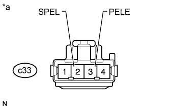
Text in Illustration *a Front view of wire harness connector
(to Lumbar Support Adjuster Assembly RH [Pelvis Motor])
Reconnect the c2 and c3 position control ECU assembly connectors.
-
Measure the voltage according to the value(s) in the table below.
Standard Voltage Tester Connection Switch Condition Specified Condition c33-2 (SPEL) - c33-3 (PELE) Pelvis switch on 4.8 to 5.1 V
NG
REPLACE POSITION CONTROL ECU ASSEMBLY Click here
OK
-
-
CHECK LUMBAR SUPPORT ADJUSTER ASSEMBLY RH
-
Temporarily replace the lumbar support adjuster assembly RH with a new or normally functioning one Click here.
-
Clear the DTCs Click here.
-
Check for DTCs Click here.
OK DTC B2658 is not output.
NG
CHECK HARNESS AND CONNECTOR (POSITION CONTROL ECU ASSEMBLY - FRONT SEAT BACK SUPPORT RH) Click here
OK
END (LUMBAR SUPPORT ADJUSTER ASSEMBLY RH WAS DEFECTIVE)
-
-
CHECK HARNESS AND CONNECTOR (POSITION CONTROL ECU ASSEMBLY - FRONT SEAT BACK SUPPORT RH)
-
Disconnect the c2 and c3 position control ECU assembly connectors.
-
Disconnect the c28 side support motor connector.
-
Measure the resistance according to the value(s) in the table below.
Standard Resistance Tester Connection Condition Specified Condition c3-16 (SSIR) - c28-2 (SISR) Always Below 1 Ω c2-20 (SGND) - c28-3 (ISRE) Always Below 1 Ω c3-16 (SSIR) - c2-20 (SGND) Always 10 kΩ or higher c3-16 (SSIR) - Body ground Always 10 kΩ or higher c2-20 (SGND) - Body ground Always 10 kΩ or higher
NG
REPAIR OR REPLACE HARNESS OR CONNECTOR
OK
-
-
CHECK POSITION CONTROL ECU ASSEMBLY (SIDE SUPPORT MOTOR CIRCUIT)
-

Text in Illustration *a Front view of wire harness connector
(to Front Seat Back Support RH [Side Support Motor])
Reconnect the c2 and c3 position control ECU assembly connectors.
-
Measure the voltage according to the value(s) in the table below.
Standard Voltage Tester Connection Switch Condition Specified Condition c28-2 (SISR) - c28-3 (ISRE) Side support switch on 4.8 to 5.1 V
NG
REPLACE POSITION CONTROL ECU ASSEMBLY Click here
OK
-
-
CHECK FRONT SEAT BACK SUPPORT RH
-
Temporarily replace the front seat back support RH with a new or normally functioning one Click here.
-
Clear the DTCs Click here.
-
Check for DTCs Click here.
OK DTC B2658 is not output.
NG
REPLACE POSITION CONTROL ECU ASSEMBLY Click here
OK
END (FRONT SEAT BACK SUPPORT RH WAS DEFECTIVE)
-
-
CHECK HARNESS AND CONNECTOR (POSITION CONTROL ECU ASSEMBLY - FRONT SEAT ADJUSTER ASSEMBLY RH)
-
Disconnect the c2 and c3 position control ECU assembly connectors.
-
Disconnect the c6 slide motor connector.
-
Measure the resistance according to the value(s) in the table below.
Standard Resistance Tester Connection Condition Specified Condition c3-8 (SSRS) - c6-2 (O/P) Always Below 1 Ω c2-20 (SGND) - c6-3 (GND) Always Below 1 Ω c3-8 (SSRS) - c2-20 (SGND) Always 10 kΩ or higher c3-8 (SSRS) - Body ground Always 10 kΩ or higher c2-20 (SGND) - Body ground Always 10 kΩ or higher
NG
REPAIR OR REPLACE HARNESS OR CONNECTOR
OK
-
-
CHECK POSITION CONTROL ECU ASSEMBLY (SLIDE MOTOR CIRCUIT)
-

Text in Illustration *a Front view of wire harness connector
(to Front Seat Adjuster Assembly RH [Slide Motor])
Reconnect the c2 and c3 position control ECU assembly connectors.
-
Measure the voltage according to the value(s) in the table below.
Standard Voltage Tester Connection Switch Condition Specified Condition c6-2 (O/P) - c6-3 (GND) Sliding switch on 4.8 to 5.1 V
NG
REPLACE POSITION CONTROL ECU ASSEMBLY Click here
OK
-
-
CHECK HARNESS AND CONNECTOR (POSITION CONTROL ECU ASSEMBLY - FRONT SEAT ADJUSTER ASSEMBLY RH)
-
Disconnect the c2 and c3 position control ECU assembly connectors.
-
Disconnect the c11 front vertical motor connector.
-
Measure the resistance according to the value(s) in the table below.
Standard Resistance Tester Connection Condition Specified Condition c3-24 (SSFV) - c11-2 (O/P) Always Below 1 Ω c2-20 (SGND) - c11-3 (GND) Always Below 1 Ω c3-24 (SSFV) - c2-20 (SGND) Always 10 kΩ or higher c3-24 (SSFV) - Body ground Always 10 kΩ or higher c2-20 (SGND) - Body ground Always 10 kΩ or higher
NG
REPAIR OR REPLACE HARNESS OR CONNECTOR
OK
-
-
CHECK POSITION CONTROL ECU ASSEMBLY (FRONT VERTICAL MOTOR CIRCUIT)
-
Text in Illustration *a Front view of wire harness connector
(to Front Seat Adjuster Assembly RH [Front Vertical Motor])
Reconnect the c2 and c3 position control ECU assembly connectors.
-
Measure the voltage according to the value(s) in the table below.
Standard Voltage Tester Connection Switch Condition Specified Condition c11-2 (O/P) - c11-3 (GND) Front vertical switch on 4.8 to 5.1 V
NG
REPLACE POSITION CONTROL ECU ASSEMBLY Click here
OK
-
-
CHECK HARNESS AND CONNECTOR (POSITION CONTROL ECU ASSEMBLY - FRONT SEAT ADJUSTER ASSEMBLY RH)
-
Disconnect the c2 and c3 position control ECU assembly connectors.
-
Disconnect the c13 lifter motor connector.
-
Measure the resistance according to the value(s) in the table below.
Standard Resistance Tester Connection Condition Specified Condition c3-10 (SSRL) - c13-2 (O/P) Always Below 1 Ω c2-20 (SGND) - c13-3 (GND) Always Below 1 Ω c3-10 (SSRL) - c2-20 (SGND) Always 10 kΩ or higher c3-10 (SSRL) - Body ground Always 10 kΩ or higher c2-20 (SGND) - Body ground Always 10 kΩ or higher
NG
REPAIR OR REPLACE HARNESS OR CONNECTOR
OK
-
-
CHECK POSITION CONTROL ECU ASSEMBLY (LIFTER MOTOR CIRCUIT)
-

Text in Illustration *a Front view of wire harness connector
(to Front Seat Adjuster Assembly RH [Lifter Motor])
Reconnect the c2 and c3 position control ECU assembly connectors.
-
Measure the voltage according to the value(s) in the table below.
Standard Voltage Tester Connection Switch Condition Specified Condition c13-2 (O/P) - c13-3 (GND) Lifter switch on 4.8 to 5.1 V
NG
REPLACE POSITION CONTROL ECU ASSEMBLY Click here
OK
-
-
CHECK HARNESS AND CONNECTOR (POSITION CONTROL ECU ASSEMBLY - FRONT SEAT ADJUSTER ASSEMBLY RH)
-
Disconnect the c2 and c3 position control ECU assembly connectors.
-
Disconnect the c9 cushion motor connector.
-
Measure the resistance according to the value(s) in the table below.
Standard Resistance Tester Connection Condition Specified Condition c3-3 (SSRC) - c9-2 (VCC) Always Below 1 Ω c2-20 (SGND) - c9-3 (GND) Always Below 1 Ω c3-3 (SSRC) - c2-20 (SGND) Always 10 kΩ or higher c3-3 (SSRC) - Body ground Always 10 kΩ or higher c2-20 (SGND) - Body ground Always 10 kΩ or higher
NG
REPAIR OR REPLACE HARNESS OR CONNECTOR
OK
-
-
CHECK POSITION CONTROL ECU ASSEMBLY (CUSHION MOTOR CIRCUIT)
-

Text in Illustration *a Front view of wire harness connector
(to Front Seat Adjuster Assembly RH [Cushion Motor])
Reconnect the c2 and c3 position control ECU assembly connectors.
-
Measure the voltage according to the value(s) in the table below.
Standard Voltage Tester Connection Switch Condition Specified Condition c9-2 (VCC) - c9-3 (GND) Cushion switch on 4.8 to 5.1 V
NG
REPLACE POSITION CONTROL ECU ASSEMBLY Click here
OK
-
-
CHECK FRONT SEAT ADJUSTER ASSEMBLY RH
-
Temporarily replace the front seat adjuster assembly RH with a new or normally functioning one Click here.
-
Clear the DTCs Click here.
-
Check for DTCs Click here.
OK DTC B2658 is not output.
NG
CHECK HARNESS AND CONNECTOR (POSITION CONTROL ECU ASSEMBLY - POWER SEAT RECLINING MOTOR ASSEMBLY) Click here
OK
END (FRONT SEAT ADJUSTER ASSEMBLY RH WAS DEFECTIVE)
-
-
CHECK HARNESS AND CONNECTOR (POSITION CONTROL ECU ASSEMBLY - POWER SEAT RECLINING MOTOR ASSEMBLY)
-
Disconnect the c2 and c3 position control ECU assembly connectors.
-
Disconnect the c25 reclining motor connector.
-
Measure the resistance according to the value(s) in the table below.
Standard Resistance Tester Connection Condition Specified Condition c3-14 (SSRR) - c25-2 (O/P) Always Below 1 Ω c2-20 (SGND) - c25-3 (GND) Always Below 1 Ω c3-14 (SSRR) - c2-20 (SGND) Always 10 kΩ or higher c3-14 (SSRR) - Body ground Always 10 kΩ or higher c2-20 (SGND) - Body ground Always 10 kΩ or higher
NG
REPAIR OR REPLACE HARNESS OR CONNECTOR
OK
-
-
CHECK POSITION CONTROL ECU ASSEMBLY (RECLINING MOTOR CIRCUIT)
-

Text in Illustration *a Front view of wire harness connector
(to Power Seat Reclining Motor Assembly)
Reconnect the c2 and c3 position control ECU assembly connectors.
-
Measure the voltage according to the value(s) in the table below.
Standard Voltage Tester Connection Switch Condition Specified Condition c25-2 (O/P) - c25-3 (GND) Reclining switch on 4.8 to 5.1 V
NG
REPLACE POSITION CONTROL ECU ASSEMBLY Click here
OK
-
-
CHECK POWER SEAT RECLINING MOTOR ASSEMBLY
-
Temporarily replace the power seat reclining motor assembly with a new or normally functioning one Click here.
-
Clear the DTCs Click here.
-
Check for DTCs Click here.
OK DTC B2658 is not output.
NG
CHECK HARNESS AND CONNECTOR (POSITION CONTROL ECU ASSEMBLY - LUMBAR SUPPORT ADJUSTER ASSEMBLY RH) Click here
OK
END (POWER SEAT RECLINING MOTOR ASSEMBLY WAS DEFECTIVE)
-
-
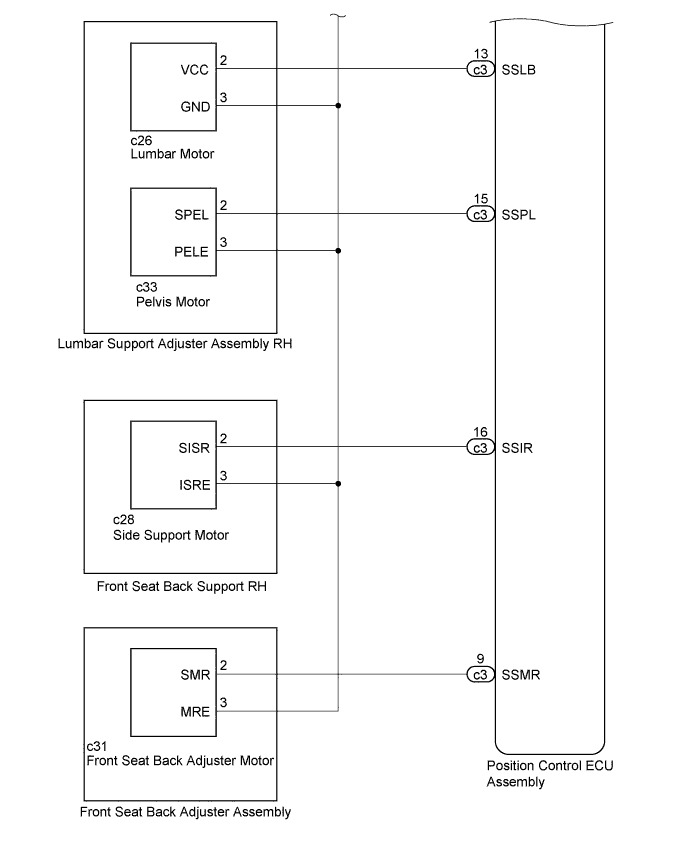
CHECK HARNESS AND CONNECTOR (POSITION CONTROL ECU ASSEMBLY - LUMBAR SUPPORT ADJUSTER ASSEMBLY RH)
-
Disconnect the c2 and c3 position control ECU assembly connectors.
-
Disconnect the c26 lumbar motor connector.
-
Measure the resistance according to the value(s) in the table below.
Standard Resistance Tester Connection Condition Specified Condition c3-13 (SSLB) - c26-2 (VCC) Always Below 1 Ω c2-20 (SGND) - c26-3 (GND) Always Below 1 Ω c3-13 (SSLB) - c2-20 (SGND) Always 10 kΩ or higher c3-13 (SSLB) - Body ground Always 10 kΩ or higher c2-20 (SGND) - Body ground Always 10 kΩ or higher
NG
REPAIR OR REPLACE HARNESS OR CONNECTOR
OK
-
-
CHECK POSITION CONTROL ECU ASSEMBLY (LUMBAR MOTOR CIRCUIT)
-

Text in Illustration *a Front view of wire harness connector
(to Lumbar Support Adjuster Assembly RH [Lumbar Motor])
Reconnect the c2 and c3 position control ECU assembly connectors.
-
Measure the voltage according to the value(s) in the table below.
Standard Voltage Tester Connection Switch Condition Specified Condition c26-2 (VCC) - c26-3 (GND) Lumbar switch on 4.8 to 5.1 V
NG
REPLACE POSITION CONTROL ECU ASSEMBLY Click here
OK
-
-
CHECK HARNESS AND CONNECTOR (POSITION CONTROL ECU ASSEMBLY - LUMBAR SUPPORT ADJUSTER ASSEMBLY RH)
-
Disconnect the c2 and c3 position control ECU assembly connectors.
-
Disconnect the c33 pelvis motor connector.
-
Measure the resistance according to the value(s) in the table below.
Standard Resistance Tester Connection Condition Specified Condition c3-15 (SSPL) - c33-2 (SPEL) Always Below 1 Ω c2-20 (SGND) - c33-3 (PELE) Always Below 1 Ω c3-15 (SSPL) - c2-20 (SGND) Always 10 kΩ or higher c3-15 (SSPL) - Body ground Always 10 kΩ or higher c2-20 (SGND) - Body ground Always 10 kΩ or higher
NG
REPAIR OR REPLACE HARNESS OR CONNECTOR
OK
-
-
CHECK POSITION CONTROL ECU ASSEMBLY (PELVIS MOTOR CIRCUIT)
-

Text in Illustration *a Front view of wire harness connector
(to Lumbar Support Adjuster Assembly RH [Pelvis Motor])
Reconnect the c2 and c3 position control ECU assembly connectors.
-
Measure the voltage according to the value(s) in the table below.
Standard Voltage Tester Connection Switch Condition Specified Condition c33-2 (SPEL) - c33-3 (PELE) Pelvis switch on 4.8 to 5.1 V
NG
REPLACE POSITION CONTROL ECU ASSEMBLY Click here
OK
-
-
CHECK LUMBAR SUPPORT ADJUSTER ASSEMBLY RH
-
Temporarily replace the lumbar support adjuster assembly RH with a new or normally functioning one Click here.
-
Clear the DTCs Click here.
-
Check for DTCs Click here.
OK DTC B2658 is not output.
NG
CHECK HARNESS AND CONNECTOR (POSITION CONTROL ECU ASSEMBLY - FRONT SEAT BACK SUPPORT RH) Click here
OK
END (LUMBAR SUPPORT ADJUSTER ASSEMBLY RH WAS DEFECTIVE)
-
-
CHECK HARNESS AND CONNECTOR (POSITION CONTROL ECU ASSEMBLY - FRONT SEAT BACK SUPPORT RH)
-
Disconnect the c2 and c3 position control ECU assembly connectors.
-
Disconnect the c28 side support motor connector.
-
Measure the resistance according to the value(s) in the table below.
Standard Resistance Tester Connection Condition Specified Condition c2-16 (SSIR) - c28-2 (SISR) Always Below 1 Ω c2-20 (SGND) - c28-3 (ISRE) Always Below 1 Ω c3-16 (SSIR) - c2-20 (SGND) Always 10 kΩ or higher c3-16 (SSIR) - Body ground Always 10 kΩ or higher c2-20 (SGND) - Body ground Always 10 kΩ or higher
NG
REPAIR OR REPLACE HARNESS OR CONNECTOR
OK
-
-
CHECK POSITION CONTROL ECU ASSEMBLY (SIDE SUPPORT MOTOR CIRCUIT)
-

Text in Illustration *a Front view of wire harness connector
(to Front Seat Back Support RH [Side Support Motor])
Reconnect the c2 and c3 position control ECU assembly connectors.
-
Measure the voltage according to the value(s) in the table below.
Standard Voltage Tester Connection Switch Condition Specified Condition c28-2 (SISR) - c28-3 (ISRE) Side support switch on 4.8 to 5.1 V
NG
REPLACE POSITION CONTROL ECU ASSEMBLY Click here
OK
-
-
CHECK FRONT SEAT BACK SUPPORT RH
-
Temporarily replace the front seat back support RH with a new or normally functioning one Click here.
-
Clear the DTCs Click here.
-
Check for DTCs Click here.
OK DTC B2658 is not output.
NG
CHECK HARNESS AND CONNECTOR (POSITION CONTROL ECU ASSEMBLY - FRONT SEAT BACK ADJUSTER ASSEMBLY) Click here
OK
END (FRONT SEAT BACK SUPPORT RH WAS DEFECTIVE)
-
-
CHECK HARNESS AND CONNECTOR (POSITION CONTROL ECU ASSEMBLY - FRONT SEAT BACK ADJUSTER ASSEMBLY)
-
Disconnect the c2 and c3 position control ECU assembly connectors.
-
Disconnect the c31 front seat back adjuster motor connector.
-
Measure the resistance according to the value(s) in the table below.
Standard Resistance Tester Connection Condition Specified Condition c3-9 (SSMR) - c31-2 (SMR) Always Below 1 Ω c2-20 (SGND) - c31-3 (MRE) Always Below 1 Ω c3-9 (SSMR) - c2-20 (SGND) Always 10 kΩ or higher c3-9 (SSMR) - Body ground Always 10 kΩ or higher c2-20 (SGND) - Body ground Always 10 kΩ or higher
NG
REPAIR OR REPLACE HARNESS OR CONNECTOR
OK
-
-
CHECK POSITION CONTROL ECU ASSEMBLY (FRONT SEAT BACK ADJUSTER MOTOR CIRCUIT)
-

Text in Illustration *a Front view of wire harness connector
(to Front Seat Back Adjuster Assembly [Front Seat Back Adjuster Motor])
Reconnect the c2 and c3 position control ECU assembly connectors.
-
Measure the voltage according to the value(s) in the table below.
Standard Voltage Tester Connection Switch Condition Specified Condition c31-2 (SMR) - c31-3 (MRE) Front seat back adjuster switch on 4.8 to 5.1 V
NG
REPLACE POSITION CONTROL ECU ASSEMBLY Click here
OK
-
-
CHECK FRONT SEAT BACK ADJUSTER ASSEMBLY
-
Temporarily replace the front seat back adjuster assembly with a new or normally functioning one Click here.
-
Clear the DTCs Click here.
-
Check for DTCs Click here.
OK DTC B2658 is not output.
NG
REPLACE POSITION CONTROL ECU ASSEMBLY Click here
OK
END (FRONT SEAT BACK ADJUSTER ASSEMBLY WAS DEFECTIVE)
-
-
CHECK HARNESS AND CONNECTOR (POSITION CONTROL ECU ASSEMBLY - FRONT SEAT ADJUSTER ASSEMBLY LH)
-
Disconnect the d4 and d5 position control ECU assembly connectors.
-
Disconnect the d7 slide motor connector.
-
Measure the resistance according to the value(s) in the table below.
Standard Resistance Tester Connection Condition Specified Condition d4-8 (SSRS) - d7-2 (VCC) Always Below 1 Ω d5-20 (SGND) - d7-3 (GND) Always Below 1 Ω d4-8 (SSRS) - d5-20 (SGND) Always 10 kΩ or higher d4-8 (SSRS) - Body ground Always 10 kΩ or higher d5-20 (SGND) - Body ground Always 10 kΩ or higher
NG
REPAIR OR REPLACE HARNESS OR CONNECTOR
OK
-
-
CHECK POSITION CONTROL ECU ASSEMBLY (SLIDE MOTOR CIRCUIT)
-

Text in Illustration *a Front view of wire harness connector
(to Front Seat Adjuster Assembly LH [Slide Motor])
Reconnect the d4 and d5 position control ECU assembly connectors.
-
Measure the voltage according to the value(s) in the table below.
Standard Voltage Tester Connection Switch Condition Specified Condition d7-2 (VCC) - d7-3 (GND) Sliding switch on 4.8 to 5.1 V
NG
REPLACE POSITION CONTROL ECU ASSEMBLY Click here
OK
-
-
CHECK HARNESS AND CONNECTOR (POSITION CONTROL ECU ASSEMBLY - FRONT SEAT ADJUSTER ASSEMBLY LH)
-
Disconnect the d4 and d5 position control ECU assembly connectors.
-
Disconnect the d10 front vertical motor connector.
-
Measure the resistance according to the value(s) in the table below.
Standard Resistance Tester Connection Condition Specified Condition d4-24 (SSFV) - d10-2 (VCC) Always Below 1 Ω d5-20 (SGND) - d10-3 (GND) Always Below 1 Ω d4-24 (SSFV) - d5-20 (SGND) Always 10 kΩ or higher d4-24 (SSFV) - Body ground Always 10 kΩ or higher d5-20 (SGND) - Body ground Always 10 kΩ or higher
NG
REPAIR OR REPLACE HARNESS OR CONNECTOR
OK
-
-
CHECK POSITION CONTROL ECU ASSEMBLY (FRONT VERTICAL MOTOR CIRCUIT)
-

Text in Illustration *a Front view of wire harness connector
(to Front Seat Adjuster Assembly LH [Front Vertical Motor])
Reconnect the d4 and d5 position control ECU assembly connectors.
-
Measure the voltage according to the value(s) in the table below.
Standard Voltage Tester Connection Switch Condition Specified Condition d10-2 (VCC) - d10-3 (GND) Front vertical switch on 4.8 to 5.1 V
NG
REPLACE POSITION CONTROL ECU ASSEMBLY Click here
OK
-
-
CHECK HARNESS AND CONNECTOR (POSITION CONTROL ECU ASSEMBLY - FRONT SEAT ADJUSTER ASSEMBLY LH)
-
Disconnect the d4 and d5 position control ECU assembly connectors.
-
Disconnect the d12 lifter motor connector.
-
Measure the resistance according to the value(s) in the table below.
Standard Resistance Tester Connection Condition Specified Condition d4-10 (SSRL) - d12-2 (VCC) Always Below 1 Ω d5-20 (SGND) - d12-3 (GND) Always Below 1 Ω d4-10 (SSRL) - d5-20 (SGND) Always 10 kΩ or higher d4-10 (SSRL) - Body ground Always 10 kΩ or higher d5-20 (SGND) - Body ground Always 10 kΩ or higher
NG
REPAIR OR REPLACE HARNESS OR CONNECTOR
OK
-
-
CHECK POSITION CONTROL ECU ASSEMBLY (LIFTER MOTOR CIRCUIT)
-

Text in Illustration *a Front view of wire harness connector
(to Front Seat Adjuster Assembly LH [Lifter Motor])
Reconnect the d4 and d5 position control ECU assembly connectors.
-
Measure the voltage according to the value(s) in the table below.
Standard Voltage Tester Connection Switch Condition Specified Condition d12-2 (VCC) - d12-3 (GND) Lifter switch on 4.8 to 5.1 V Result Result Proceed to OK (for Ottoman) A OK (except Ottoman) B NG C
B
CHECK HARNESS AND CONNECTOR (POSITION CONTROL ECU ASSEMBLY - FRONT SEAT ADJUSTER ASSEMBLY LH) Click here
C
REPLACE POSITION CONTROL ECU ASSEMBLY Click here
A
-
-
CHECK HARNESS AND CONNECTOR (POSITION CONTROL ECU ASSEMBLY - FRONT SEAT ADJUSTER ASSEMBLY LH)
-
Disconnect the d4 and d5 position control ECU assembly connectors.
-
Disconnect the d35 ottoman motor connector.
-
Measure the resistance according to the value(s) in the table below.
Standard Resistance Tester Connection Condition Specified Condition d4-3 (SSRC) - d35-2 (P) Always Below 1 Ω d5-20 (SGND) - d35-3 (GND) Always Below 1 Ω d4-3 (SSRC) - d5-20 (SGND) Always 10 kΩ or higher d4-3 (SSRC) - Body ground Always 10 kΩ or higher d5-20 (SGND) - Body ground Always 10 kΩ or higher
NG
REPAIR OR REPLACE HARNESS OR CONNECTOR
OK
-
-
CHECK POSITION CONTROL ECU ASSEMBLY (OTTOMAN MOTOR CIRCUIT)
-

Text in Illustration *a Front view of wire harness connector
(to Front Seat Adjuster Assembly LH [Ottoman Motor])
Reconnect the d4 and d5 position control ECU assembly connectors.
-
Measure the voltage according to the value(s) in the table below.
Standard Voltage Tester Connection Switch Condition Specified Condition d35-2 (P) - d35-3 (GND) Ottoman switch on 4.8 to 5.1 V
NG
REPLACE POSITION CONTROL ECU ASSEMBLY Click here
OK
-
-
CHECK FRONT SEAT ADJUSTER ASSEMBLY LH
-
Temporarily replace the front seat adjuster assembly LH with a new or normally functioning one Click here.
-
Clear the DTCs Click here.
-
Check for DTCs Click here.
OK DTC B2658 is not output.
NG
CHECK HARNESS AND CONNECTOR (POSITION CONTROL ECU ASSEMBLY - POWER SEAT RECLINING MOTOR ASSEMBLY) Click here
OK
END (FRONT SEAT ADJUSTER ASSEMBLY LH WAS DEFECTIVE)
-
-
CHECK HARNESS AND CONNECTOR (POSITION CONTROL ECU ASSEMBLY - FRONT SEAT ADJUSTER ASSEMBLY LH)
-
Disconnect the d4 and d5 position control ECU assembly connectors.
-
Disconnect the d9 cushion motor connector.
-
Measure the resistance according to the value(s) in the table below.
Standard Resistance Tester Connection Condition Specified Condition d4-3 (SSRC) - d9-2 (P) Always Below 1 Ω d5-20 (SGND) - d9-3 (GND) Always Below 1 Ω d4-3 (SSRC) - d5-20 (SGND) Always 10 kΩ or higher d4-3 (SSRC) - Body ground Always 10 kΩ or higher d5-20 (SGND) - Body ground Always 10 kΩ or higher
NG
REPAIR OR REPLACE HARNESS OR CONNECTOR
OK
-
-
CHECK POSITION CONTROL ECU ASSEMBLY (CUSHION MOTOR CIRCUIT)
-
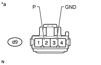
Text in Illustration *a Front view of wire harness connector
(to Front Seat Adjuster Assembly LH [Cushion Motor])
Reconnect the d4 and d5 position control ECU assembly connectors.
-
Measure the voltage according to the value(s) in the table below.
Standard Voltage Tester Connection Switch Condition Specified Condition d9-2 (P) - d9-3 (GND) Cushion switch on 4.8 to 5.1 V
NG
REPLACE POSITION CONTROL ECU ASSEMBLY Click here
OK
-
-
CHECK FRONT SEAT ADJUSTER ASSEMBLY LH
-
Temporarily replace the front seat adjuster assembly LH with a new or normally functioning one Click here.
-
Clear the DTCs Click here.
-
Check for DTCs Click here.
OK DTC B2658 is not output.
NG
CHECK HARNESS AND CONNECTOR (POSITION CONTROL ECU ASSEMBLY - POWER SEAT RECLINING MOTOR ASSEMBLY) Click here
OK
END (FRONT SEAT ADJUSTER ASSEMBLY LH WAS DEFECTIVE)
-
-
CHECK HARNESS AND CONNECTOR (POSITION CONTROL ECU ASSEMBLY - POWER SEAT RECLINING MOTOR ASSEMBLY)
-
Disconnect the d4 and d5 position control ECU assembly connectors.
-
Disconnect the d25 power seat reclining motor connector.
-
Measure the resistance according to the value(s) in the table below.
Standard Resistance Tester Connection Condition Specified Condition d4-14 (SSRR) - d25-2 (VCC) Always Below 1 Ω d5-20 (SGND) - d25-3 (GND) Always Below 1 Ω d4-14 (SSRR) - d5-20 (SGND) Always 10 kΩ or higher d4-14 (SSRR) - Body ground Always 10 kΩ or higher d5-20 (SGND) - Body ground Always 10 kΩ or higher
NG
REPAIR OR REPLACE HARNESS OR CONNECTOR
OK
-
-
CHECK POSITION CONTROL ECU ASSEMBLY (RECLINING MOTOR CIRCUIT)
-

Text in Illustration *a Front view of wire harness connector
(to Power Seat Reclining Motor Assembly)
Reconnect the d4 and d5 position control ECU assembly connectors.
-
Measure the voltage according to the value(s) in the table below.
Standard Voltage Tester Connection Switch Condition Specified Condition d25-2 (VCC) - d25-3 (GND) Reclining switch on 4.8 to 5.1 V
NG
REPLACE POSITION CONTROL ECU ASSEMBLY Click here
OK
-
-
CHECK POWER SEAT RECLINING MOTOR ASSEMBLY
-
Temporarily replace the power seat reclining motor assembly with a new or normally functioning one Click here.
-
Clear the DTCs Click here.
-
Check for DTCs Click here.
OK DTC B2658 is not output.
NG
CHECK HARNESS AND CONNECTOR (POSITION CONTROL ECU ASSEMBLY - LUMBAR SUPPORT ADJUSTER ASSEMBLY LH) Click here
OK
END (POWER SEAT RECLINING MOTOR ASSEMBLY WAS DEFECTIVE)
-
-
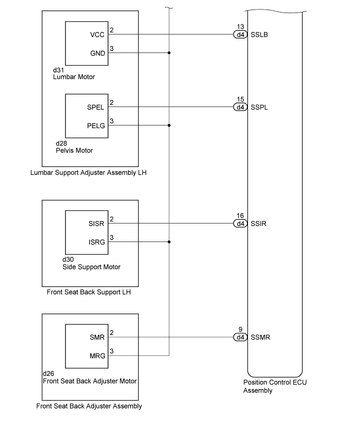
CHECK HARNESS AND CONNECTOR (POSITION CONTROL ECU ASSEMBLY - LUMBAR SUPPORT ADJUSTER ASSEMBLY LH)
-
Disconnect the d4 and d5 position control ECU assembly connectors.
-
Disconnect the d31 lumbar motor connector.
-
Measure the resistance according to the value(s) in the table below.
Standard Resistance Tester Connection Condition Specified Condition d4-13 (SSLB) - d31-2 (VCC) Always Below 1 Ω d5-20 (SGND) - d31-3 (GND) Always Below 1 Ω d4-13 (SSLB) - d5-20 (SGND) Always 10 kΩ or higher d4-13 (SSLB) - Body ground Always 10 kΩ or higher d5-20 (SGND) - Body ground Always 10 kΩ or higher
NG
REPAIR OR REPLACE HARNESS OR CONNECTOR
OK
-
-
CHECK POSITION CONTROL ECU ASSEMBLY (LUMBAR MOTOR CIRCUIT)
-

Text in Illustration *a Front view of wire harness connector
(to Lumbar Support Adjuster Assembly LH [Lumbar Motor])
Reconnect the d4 and d5 position control ECU assembly connectors.
-
Measure the voltage according to the value(s) in the table below.
Standard Voltage Tester Connection Switch Condition Specified Condition d31-2 (VCC) - d31-3 (GND) Lumbar switch on 4.8 to 5.1 V
NG
REPLACE POSITION CONTROL ECU ASSEMBLY Click here
OK
-
-
CHECK HARNESS AND CONNECTOR (POSITION CONTROL ECU ASSEMBLY - LUMBAR SUPPORT ADJUSTER ASSEMBLY LH)
-
Disconnect the d4 and d5 position control ECU assembly connectors.
-
Disconnect the d28 pelvis motor connector.
-
Measure the resistance according to the value(s) in the table below.
Standard Resistance Tester Connection Condition Specified Condition d4-15 (SSPL) - d28-2 (SPEL) Always Below 1 Ω d5-20 (SGND) - d28-3 (PELG) Always Below 1 Ω d4-15 (SSPL) - d5-20 (SGND) Always 10 kΩ or higher d4-15 (SSPL) - Body ground Always 10 kΩ or higher d5-20 (SGND) - Body ground Always 10 kΩ or higher
NG
REPAIR OR REPLACE HARNESS OR CONNECTOR
OK
-
-
CHECK POSITION CONTROL ECU ASSEMBLY (PELVIS MOTOR CIRCUIT)
-

Text in Illustration *a Front view of wire harness connector
(to Lumbar Support Adjuster Assembly LH [Pelvis Motor])
Reconnect the d4 and d5 position control ECU assembly connectors.
-
Measure the voltage according to the value(s) in the table below.
Standard Voltage Tester Connection Switch Condition Specified Condition d28-2 (SPEL) - d28-3 (PELG) Pelvis switch on 4.8 to 5.1 V
NG
REPLACE POSITION CONTROL ECU ASSEMBLY Click here
OK
-
-
CHECK LUMBAR SUPPORT ADJUSTER ASSEMBLY LH
-
Temporarily replace the lumbar support adjuster assembly LH with a new or normally functioning one Click here.
-
Clear the DTCs Click here.
-
Check for DTCs Click here.
OK DTC B2658 is not output.
NG
CHECK HARNESS AND CONNECTOR (POSITION CONTROL ECU ASSEMBLY - FRONT SEAT BACK SUPPORT LH) Click here
OK
END (LUMBAR SUPPORT ADJUSTER ASSEMBLY LH WAS DEFECTIVE)
-
-
CHECK HARNESS AND CONNECTOR (POSITION CONTROL ECU ASSEMBLY - FRONT SEAT BACK SUPPORT LH)
-
Disconnect the d4 and d5 position control ECU assembly connectors.
-
Disconnect the d30 side support motor connector.
-
Measure the resistance according to the value(s) in the table below.
Standard Resistance Tester Connection Condition Specified Condition d4-16 (SSIR) - d30-2 (SISR) Always Below 1 Ω d5-20 (SGND) - d30-3 (ISRG) Always Below 1 Ω d4-16 (SSIR) - d5-20 (SGND) Always 10 kΩ or higher d4-16 (SSIR) - Body ground Always 10 kΩ or higher d5-20 (SGND) - Body ground Always 10 kΩ or higher
NG
REPAIR OR REPLACE HARNESS OR CONNECTOR
OK
-
-
CHECK POSITION CONTROL ECU ASSEMBLY (SIDE SUPPORT CIRCUIT)
-
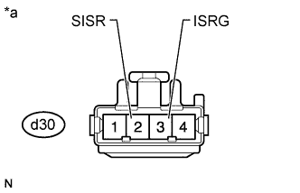
Text in Illustration *a Front view of wire harness connector
(to Front Seat Back Support LH [Side Support Motor])
Reconnect the d4 and d5 position control ECU assembly connectors.
-
Measure the voltage according to the value(s) in the table below.
Standard Voltage Tester Connection Switch Condition Specified Condition d30-2 (SISR) - d30-3 (ISRG) Side support switch on 4.8 to 5.1 V
NG
REPLACE POSITION CONTROL ECU ASSEMBLY Click here
OK
-
-
CHECK FRONT SEAT BACK SUPPORT LH
-
Temporarily replace the front seat back support LH with a new or normally functioning one Click here.
-
Clear the DTCs Click here.
-
Check for DTCs Click here.
OK DTC B2658 is not output.
NG
CHECK HARNESS AND CONNECTOR (POSITION CONTROL ECU ASSEMBLY - FRONT SEAT BACK ADJUSTER ASSEMBLY) Click here
OK
END (FRONT SEAT BACK SUPPORT LH WAS DEFECTIVE)
-
-
CHECK HARNESS AND CONNECTOR (POSITION CONTROL ECU ASSEMBLY - FRONT SEAT BACK ADJUSTER ASSEMBLY)
-
Disconnect the d4 and d5 position control ECU assembly connectors.
-
Disconnect the d26 front seat back adjuster motor connector.
-
Measure the resistance according to the value(s) in the table below.
Standard Resistance Tester Connection Condition Specified Condition d4-9 (SSMR) - d26-2 (SMR) Always Below 1 Ω d5-20 (SGND) - d26-3 (MRG) Always Below 1 Ω d4-9 (SSMR) - d5-20 (SGND) Always 10 kΩ or higher d4-9 (SSMR) - Body ground Always 10 kΩ or higher d5-20 (SGND) - Body ground Always 10 kΩ or higher
NG
REPAIR OR REPLACE HARNESS OR CONNECTOR
OK
-
-
CHECK POSITION CONTROL ECU ASSEMBLY (FRONT SEAT BACK ADJUSTER MOTOR CIRCUIT)
-

Text in Illustration *a Front view of wire harness connector
(to Front Seat Back Adjuster Assembly [Front Seat Back Adjuster Motor])
Reconnect the d4 and d5 position control ECU assembly connectors.
-
Measure the voltage according to the value(s) in the table below.
Standard Voltage Tester Connection Switch Condition Specified Condition d26-2 (SMR) - d26-3 (MRG) Front seat back adjuster switch on 4.8 to 5.1 V
NG
REPLACE POSITION CONTROL ECU ASSEMBLY Click here
OK
-
-
CHECK FRONT SEAT BACK ADJUSTER ASSEMBLY
-
Temporarily replace the front seat back adjuster assembly with a new or normally functioning one Click here.
-
Clear the DTCs Click here.
-
Check for DTCs Click here.
OK DTC B2658 is not output.
NG
REPLACE POSITION CONTROL ECU ASSEMBLY Click here
OK
END (FRONT SEAT BACK ADJUSTER ASSEMBLY WAS DEFECTIVE)
-