FRONT POWER SEAT CONTROL SYSTEM (for RHD), Diagnostic DTC:B2653

| DTC Code | DTC Name |
|---|---|
| B2653 | Lifter Sensor Malfunction |
DESCRIPTION
-
*1: for Driver Side (Standard Seat Type)
-
*2: for Driver Side (Sports Seat Type, Luxury Seat Type)
-
*3: for Front Passenger Side (Luxury Seat Type)
When the power seat switch assembly*1 or position control ECU assembly*2, *3 does not receive a sensor signal despite upward or downward movement of the seat by power seat motor operation, this DTC is stored.
| DTC Code | DTC Detection Condition | Trouble Area |
|---|---|---|
| B2653 | The upward and downward lock detection position of the sensor is the same. |
|
WIRING DIAGRAM
-
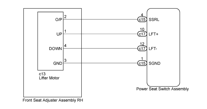
for Driver Side (Standard Seat Type):
-
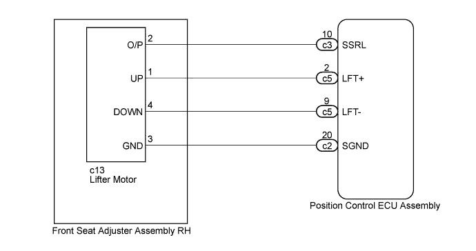
for Driver Side (Sports Seat Type, Luxury Seat Type):
-
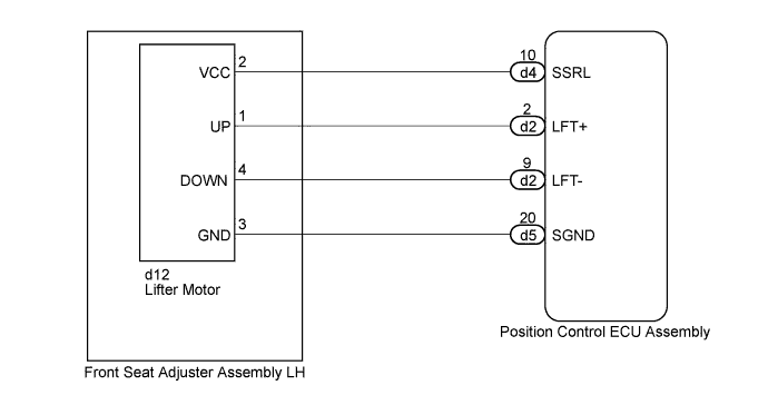
for Front Passenger Side (Luxury Seat Type):
INSPECTION PROCEDURE
PROCEDURE
-
CHECK FOR DTC
-
Check the parts which the DTCs have been output from Click here.
Result Result Proceed to DTC output from "Driver Seat" A DTC output from "Passenger Seat" B
B 
PERFORM ACTIVE TEST USING GTS (LIFTER OPERATION) Click here
A 
-
-
PERFORM ACTIVE TEST USING GTS (LIFTER OPERATION)
-
Turn the power switch off.
-
Connect the GTS to the DLC3.
-
Turn the power switch on (IG).
-
Turn the GTS on.
-
Enter the following menus: Body Electrical / Driver Seat / Active Test.
-
Perform the Active Test according to the display on the GTS.
Driver Seat Tester Display Test Part Control Range Diagnostic Note Lifter Operation Seat lifter operation Up / OFF / Down - OK Motor operates normally. Result Result Proceed to OK (for Standard Seat Type) A OK (for Sports Seat Type, Luxury Seat Type) B NG C
B
CHECK POSITION CONTROL ECU ASSEMBLY (LIFTER MOTOR CIRCUIT) Click here
C
INSPECT FRONT SEAT ADJUSTER ASSEMBLY RH (LIFTER MOTOR) Click here
A
-
-
CHECK POWER SEAT SWITCH ASSEMBLY (LIFTER MOTOR CIRCUIT)
-

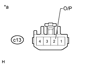
Text in Illustration *a Front view of wire harness connector
(to Front Seat Adjuster Assembly RH [Lifter Motor])
Disconnect the lifter motor connector.
-
Measure the voltage according to the value(s) in the table below.
Standard Voltage Tester Connection Switch Condition Specified Condition c13-2 (O/P) - c13-3 (GND) Lifter switch on 4.8 to 5.1 V
NG
CHECK HARNESS AND CONNECTOR (POWER SEAT SWITCH ASSEMBLY - FRONT SEAT ADJUSTER ASSEMBLY RH) Click here
OK
-
-
CHECK FRONT SEAT ADJUSTER ASSEMBLY RH (LIFTER MOTOR)
-
Text in Illustration *a Component with harness connected
(Front Seat Adjuster Assembly RH [Lifter Motor])
Reconnect the lifter motor connector.
-
Measure the voltage according to the value(s) in the table below.
Standard Voltage Tester Connection Switch Condition Specified Condition c13-2 (O/P) - Body ground Lifter switch on 4.5 to 4.8 V
NG 
REPLACE FRONT SEAT ADJUSTER ASSEMBLY RH (LIFTER MOTOR) Click here
OK 
REPLACE POWER SEAT SWITCH ASSEMBLY Click here
-
-
CHECK HARNESS AND CONNECTOR (POWER SEAT SWITCH ASSEMBLY - FRONT SEAT ADJUSTER ASSEMBLY RH)
-
Disconnect the c15 power seat switch assembly connector.
-
Measure the resistance according to the value(s) in the table below.
Standard Resistance Tester Connection Condition Specified Condition c15-4 (SSRL) - c13-2 (O/P) Always Below 1 Ω c15-1 (SGND) - c13-3 (GND) Always Below 1 Ω c15-4 (SSRL) - Body ground Always 10 kΩ or higher c15-1 (SGND) - Body ground Always 10 kΩ or higher
NG
REPAIR OR REPLACE HARNESS OR CONNECTOR
OK
REPLACE POWER SEAT SWITCH ASSEMBLY Click here
-
-
CHECK POSITION CONTROL ECU ASSEMBLY (LIFTER MOTOR CIRCUIT)
-
Text in Illustration *a Front view of wire harness connector
(to Front Seat Adjuster Assembly RH [Lifter Motor])
Disconnect the lifter motor connector.
-
Measure the voltage according to the value(s) in the table below.
Standard Voltage Tester Connection Switch Condition Specified Condition c13-2 (O/P) - c13-3 (GND) Lifter switch on 4.8 to 5.1 V
NG
CHECK HARNESS AND CONNECTOR (POSITION CONTROL ECU ASSEMBLY - FRONT SEAT ADJUSTER ASSEMBLY RH) Click here
OK
-
-
CHECK FRONT SEAT ADJUSTER ASSEMBLY RH (LIFTER MOTOR)
-
Text in Illustration *a Component with harness connected
(Front Seat Adjuster Assembly RH [Lifter Motor])
Reconnect the lifter motor connector.
-
Measure the voltage according to the value(s) in the table below.
Standard Voltage Tester Connection Switch Condition Specified Condition c13-2 (O/P) - Body ground Lifter switch on 4.5 to 4.8 V Result Result Proceed to OK (for Sports Seat Type) A OK (for Luxury Seat Type) B NG (for Sports Seat Type) C NG (for Luxury Seat Type) D
B
REPLACE POSITION CONTROL ECU ASSEMBLY Click here
C
REPLACE FRONT SEAT ADJUSTER ASSEMBLY RH (LIFTER MOTOR) Click here
D
REPLACE FRONT SEAT ADJUSTER ASSEMBLY RH (LIFTER MOTOR) Click here
A
REPLACE POSITION CONTROL ECU ASSEMBLY Click here
-
-
CHECK HARNESS AND CONNECTOR (POSITION CONTROL ECU ASSEMBLY - FRONT SEAT ADJUSTER ASSEMBLY RH)
-
Disconnect the c2 and c3 position control ECU assembly connectors.
-
Measure the resistance according to the value(s) in the table below.
Standard Resistance Tester Connection Condition Specified Condition c3-10 (SSRL) - c13-2 (O/P) Always Below 1 Ω c2-20 (SGND) - c13-3 (GND) Always Below 1 Ω c3-10 (SSRL) - Body ground Always 10 kΩ or higher c2-20 (SGND) - Body ground Always 10 kΩ or higher Result Result Proceed to OK (for Sports Seat Type) A OK (for Luxury Seat Type) B NG C
B
REPLACE POSITION CONTROL ECU ASSEMBLY Click here
C
REPAIR OR REPLACE HARNESS OR CONNECTOR
A
REPLACE POSITION CONTROL ECU ASSEMBLY Click here
-
-
INSPECT FRONT SEAT ADJUSTER ASSEMBLY RH (LIFTER MOTOR)
-
Text in Illustration *a Component without harness connected
(Front Seat Adjuster Assembly RH [Lifter Motor])
Disconnect the c13 lifter motor connector.
-
Check if the lifter motor moves smoothly when the battery is connected to the lifter motor connector terminals.
OK Measurement Condition Operational Direction Battery positive (+) → 1 (UP)
Battery negative (-) → 4 (DOWN)
Upward Battery positive (+) → 4 (DOWN)
Battery negative (-) → 1 (UP)
Downward Result Result Proceed to OK (for Standard Seat Type) A OK (for Sports Seat Type, Luxury Seat Type) B NG (for Standard Seat Type) C NG (for Sports Seat Type) D NG (for Luxury Seat Type) E
B
CHECK HARNESS AND CONNECTOR (POSITION CONTROL ECU ASSEMBLY - FRONT SEAT ADJUSTER ASSEMBLY RH) Click here
C
REPLACE FRONT SEAT ADJUSTER ASSEMBLY RH (LIFTER MOTOR) Click here
D
REPLACE FRONT SEAT ADJUSTER ASSEMBLY RH (LIFTER MOTOR) Click here
E
REPLACE FRONT SEAT ADJUSTER ASSEMBLY RH (LIFTER MOTOR) Click here
A
-
-
CHECK HARNESS AND CONNECTOR (POWER SEAT SWITCH ASSEMBLY - FRONT SEAT ADJUSTER ASSEMBLY RH)
-
Disconnect the c17 power seat switch assembly connector.
-
Measure the resistance according to the value(s) in the table below.
Standard Resistance Tester Connection Condition Specified Condition c17-10 (LFT+) - c13-1 (UP) Always Below 1 Ω c17-12 (LFT-) - c13-4 (DOWN) Always Below 1 Ω c17-10 (LFT+) - Body ground Always 10 kΩ or higher c17-12 (LFT-) - Body ground Always 10 kΩ or higher
NG
REPAIR OR REPLACE HARNESS OR CONNECTOR
OK
REPLACE POWER SEAT SWITCH ASSEMBLY Click here
-
-
CHECK HARNESS AND CONNECTOR (POSITION CONTROL ECU ASSEMBLY - FRONT SEAT ADJUSTER ASSEMBLY RH)
-
Disconnect the c5 position control ECU assembly connector.
-
Measure the resistance according to the value(s) in the table below.
Standard Resistance Tester Connection Condition Specified Condition c5-2 (LFT+) - c13-1 (UP) Always Below 1 Ω c5-9 (LFT-) - c13-4 (DOWN) Always Below 1 Ω c5-2 (LFT+) - Body ground Always 10 kΩ or higher c5-9 (LFT-) - Body ground Always 10 kΩ or higher Result Result Proceed to OK (for Sports Seat Type) A OK (for Luxury Seat Type) B NG C
B
REPLACE POSITION CONTROL ECU ASSEMBLY Click here
C
REPAIR OR REPLACE HARNESS OR CONNECTOR
A
REPLACE POSITION CONTROL ECU ASSEMBLY Click here
-
-
PERFORM ACTIVE TEST USING GTS (LIFTER OPERATION)
-
Turn the power switch off.
-
Connect the GTS to the DLC3.
-
Turn the power switch on (IG).
-
Turn the GTS on.
-
Enter the following menus: Body Electrical / Passenger Seat / Active Test.
-
Perform the Active Test according to the display on the GTS.
Passenger Seat Tester Display Test Part Control Range Diagnostic Note Lifter Operation Seat lifter operation Up / OFF / Down - OK Motor operates normally.
NG
INSPECT FRONT SEAT ADJUSTER ASSEMBLY LH (LIFTER MOTOR) Click here
OK
-
-
CHECK POSITION CONTROL ECU ASSEMBLY (LIFTER MOTOR CIRCUIT)
-
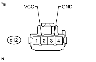
Text in Illustration *a Front view of wire harness connector
(to Front Seat Adjuster Assembly LH [Lifter Motor])
Disconnect the lifter motor connector.
-
Measure the voltage according to the value(s) in the table below.
Standard Voltage Tester Connection Switch Condition Specified Condition d12-2 (VCC) - d12-3 (GND) Lifter switch on 4.8 to 5.1 V
NG
CHECK HARNESS AND CONNECTOR (POSITION CONTROL ECU ASSEMBLY - FRONT SEAT ADJUSTER ASSEMBLY LH) Click here
OK
-
-
CHECK FRONT SEAT ADJUSTER ASSEMBLY LH (LIFTER MOTOR)
-
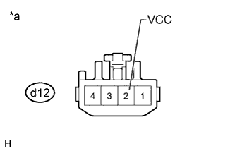
Text in Illustration *a Component with harness connected
(Front Seat Adjuster Assembly LH [Lifter Motor])
Reconnect the lifter motor connector.
-
Measure the voltage according to the value(s) in the table below.
Standard Voltage Tester Connection Switch Condition Specified Condition d12-2 (VCC) - Body ground Lifter switch on 4.5 to 4.8 V
NG
REPLACE FRONT SEAT ADJUSTER ASSEMBLY LH (LIFTER MOTOR) Click here
OK
REPLACE POSITION CONTROL ECU ASSEMBLY Click here
-
-
CHECK HARNESS AND CONNECTOR (POSITION CONTROL ECU ASSEMBLY - FRONT SEAT ADJUSTER ASSEMBLY LH)
-
Disconnect the d4 and d5 position control ECU assembly connectors.
-
Measure the resistance according to the value(s) in the table below.
Standard Resistance Tester Connection Condition Specified Condition d4-10 (SSRL) - d12-2 (VCC) Always Below 1 Ω d5-20 (SGND) - d12-3 (GND) Always Below 1 Ω d4-10 (SSRL) - Body ground Always 10 kΩ or higher d5-20 (SGND) - Body ground Always 10 kΩ or higher
NG
REPAIR OR REPLACE HARNESS OR CONNECTOR
OK
REPLACE POSITION CONTROL ECU ASSEMBLY Click here
-
-
INSPECT FRONT SEAT ADJUSTER ASSEMBLY LH (LIFTER MOTOR)
-
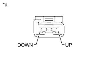
Text in Illustration *a Component without harness connected
(Front Seat Adjuster Assembly LH [Lifter Motor])
Disconnect the d12 lifter motor connector.
-
Check if the lifter motor moves smoothly when the battery is connected to the lifter motor connector terminals.
OK Measurement Condition Operational Direction Battery positive (+) → 1 (UP)
Battery negative (-) → 4 (DOWN)
Upward Battery positive (+) → 4 (DOWN)
Battery negative (-) → 1 (UP)
Downward
NG
REPLACE FRONT SEAT ADJUSTER ASSEMBLY LH (LIFTER MOTOR) Click here
OK
-
-
CHECK HARNESS AND CONNECTOR (POSITION CONTROL ECU ASSEMBLY - FRONT SEAT ADJUSTER ASSEMBLY LH)
-
Disconnect the d2 position control ECU assembly connector.
-
Measure the resistance according to the value(s) in the table below.
Standard Resistance Tester Connection Condition Specified Condition d2-2 (LFT+) - d12-1 (UP) Always Below 1 Ω d2-9 (LFT-) - d12-4 (DOWN) Always Below 1 Ω d2-2 (LFT+) - Body ground Always 10 kΩ or higher d2-9 (LFT-) - Body ground Always 10 kΩ or higher
NG
REPAIR OR REPLACE HARNESS OR CONNECTOR
OK
REPLACE POSITION CONTROL ECU ASSEMBLY Click here
-