FRONT POWER SEAT CONTROL SYSTEM (for LHD) TERMINALS OF ECU

-
CHECK POWER SEAT SWITCH ASSEMBLY (for Driver Side, Standard Seat Type)

-
Disconnect the d15 and d16 power seat switch assembly connectors.
-
Measure the voltage and resistance according to the value(s) in the table below.
Terminal No. (Symbol) Wiring Color Terminal Description Condition Specified Condition d15-2 (GND) - Body ground B - Body ground Ground Always Below 1 Ω d15-7 (+B) - d15-2 (GND) G - B Power source Always 11 to 14 V d16-12 (SYSB) - d15-2 (GND) B - B System power source Always 11 to 14 V If the result is not as specified, there may be a malfunction on the wire harness side.
-
Reconnect the d15 and d16 connectors to the power seat switch assembly.
-
Measure the voltage and resistance according to the value(s) in the table below.
Terminal No. (Symbol) Wiring Color Terminal Description Condition Specified Condition d15-6 (+B2) - d15-1 (GND2) Y - W Lumbar support adjuster power source Always 11 to 14 V d15-1 (GND2) - Body ground W - Body ground Lumbar support adjuster ground Always Below 1 Ω d15-3 (SLD+) - d15-2 (GND) B - B Sliding motor signal (Forward) Slide switch off Below 1 V Slide switch on (Forward) 11 to 14 V d15-4 (SLD-) - d15-2 (GND) P - B Sliding motor signal (Rearward) Slide switch off Below 1 V Slide switch on (Rearward) 11 to 14 V d15-5 (FRV-) - d15-2 (GND) W - B Front vertical motor signal (Downward) Front vertical switch off Below 1 V Front vertical switch on (Downward) 11 to 14 V d15-8 (FRV+) - d15-2 (GND) R - B Front vertical motor signal (Upward) Front vertical switch off Below 1 V Front vertical switch on (Upward) 11 to 14 V d15-9 (RCL+) - d15-2 (GND) V - B Reclining motor signal (Forward) Reclining switch off Below 1 V Reclining switch on (Forward) 11 to 14 V d15-11 (RCL-) - d15-2 (GND) G - B Reclining motor signal (Rearward) Reclining switch off Below 1 V Reclining switch on (Rearward) 11 to 14 V d15-10 (LFT+) - d15-2 (GND) Y - B Lifter motor signal (Upward) Lifter switch off Below 1 V Lifter switch on (Upward) 11 to 14 V d15-12 (LFT-) - d15-2 (GND) L - B Lifter motor signal (downward) Lifter switch off Below 1 V Lifter switch on (Downward) 11 to 14 V d16-1 (SGND) - d15-2 (GND) BR - B Position sensor ground Always Below 1 Ω d16-3 (SSFV) - d16-1 (SGND) GR - BR Front vertical position signal Front vertical function operating 4.5 to 4.8 V d16-4 (SSRL) - d16-1 (SGND) R - BR Lifter position signal Lifter function operating 4.5 to 4.8 V d16-5 (SSRS) - d16-1 (SGND) W - BR Slide position signal Slide function operating 4.5 to 4.8 V d16-11 (SSRR) - d16-1 (SGND) GR - BR Reclining position signal Reclining function operating 4.5 to 4.8 V
-
-
CHECK POSITION CONTROL ECU ASSEMBLY (for Driver Side, Sports Seat Type, Luxury Seat Type)

-
Disconnect the d4 and d5 position control ECU assembly connectors.
-
Measure the voltage and resistance according to the value(s) in the table below.
Terminal No. (Symbol) Wiring Color Terminal Description Condition Specified Condition d5-1 (GND2) - Body ground B - Body ground Ground Always Below 1 Ω d5-2 (GND) - Body ground B - Body ground Ground Always Below 1 Ω d4-1 (+B2) - d5-2 (GND) Y - B Power source Always 11 to 14 V d4-2 (+B) - d5-2 (GND) G - B Power source Always 11 to 14 V d5-18 (SYSB) - d5-2 (GND) B - B System power source Always 11 to 14 V If the result is not as specified, there may be a malfunction on the wire harness side.
-
Reconnect the d4 and d5 connectors to the position control ECU assembly.
-
Measure the voltage and resistance according to the value(s) in the table below.
Terminal No. (Symbol) Wiring Color Terminal Description Condition Specified Condition d2-6 (SLD+) - d5-2 (GND) B - B Sliding motor signal (Forward) Slide switch off Below 1 V Slide switch on (Forward) 11 to 14 V d2-3 (SLD-) - d5-2 (GND) P - B Sliding motor signal (Backward) Slide switch off Below 1 V Slide switch on (Backward) 11 to 14 V d2-4 (FRV-) - d5-2 (GND) W - B Front vertical motor signal (Downward) Front vertical switch off Below 1 V Front vertical switch on (Downward) 11 to 14 V d2-7 (FRV+) - d5-2 (GND) R - B Front vertical motor signal (Upward) Front vertical switch off Below 1 V Front vertical switch on (Upward) 11 to 14 V d2-8 (RCL+) - d5-2 (GND) V - B Reclining motor signal (Forward) Reclining switch off Below 1 V Reclining switch on (Forward) 11 to 14 V d2-10 (RCL-) - d5-2 (GND) G - B Reclining motor signal (Backward) Reclining switch off Below 1 V Reclining switch on (Backward) 11 to 14 V d2-2 (LFT+) - d5-2 (GND) Y - B Lifter motor signal (Upward) Lifter switch off Below 1 V Lifter switch on (Upward) 11 to 14 V d2-9 (LFT-) - d5-2 (GND) L - B Lifter motor signal (Downward) Lifter switch off Below 1 V Lifter switch on (Downward) 11 to 14 V d4-5 (L+) - d5-2 (GND) V - B Lumbar motor signal (Forward) Lumbar switch off Below 1 V Lumbar switch on (Forward) 11 to 14 V d5-3 (L-) - d5-2 (GND) BE - B Lumbar motor signal (Backward) Lumbar switch off Below 1 V Lumbar switch on (Backward) 11 to 14 V d3-4 (PEL+) - d5-2 (GND) R - B Pelvis motor signal (Forward) Pelvis switch off Below 1 V Pelvis switch on (Forward) 11 to 14 V d3-2 (PEL-) - d5-2 (GND) B - B Pelvis motor signal (Backward) Pelvis switch off Below 1 V Pelvis switch on (Backward) 11 to 14 V d3-1 (MR+) - d5-2 (GND)* G - B Front seat back adjuster motor signal (Forward) Front seat back adjuster switch off Below 1 V Front seat back adjuster switch on (Forward) 11 to 14 V d3-5 (MR-) - d5-2 (GND)* L - B Front seat back adjuster motor signal (Backward) Front seat back adjuster switch off Below 1 V Front seat back adjuster switch on (Backward) 11 to 14 V d4-6 (C+) - d5-2 (GND) GR - B Cushion motor signal (Forward) Cushion switch off Below 1 V Cushion switch on (Forward) 11 to 14 V d5-4 (C-) - d5-2 (GND) LG - B Cushion motor signal (Backward) Cushion switch off Below 1 V Cushion switch on (Backward) 11 to 14 V d3-3 (ISR+) - d5-2 (GND) V - B Side support motor signal (Paddle open) Side support switch off Below 1 V Side support switch on (Paddle open) 11 to 14 V d3-6 (ISR-) - d5-2 (GND) P - B Side support motor signal (Paddle close) Side support switch off Below 1 V Side support switch on (Paddle close) 11 to 14 V d5-20 (SGND) - d5-2 (GND) BR - B Position sensor ground Always Below 1 Ω d4-24 (SSFV) - d5-20 (SGND) GR - BR Front vertical position signal Front vertical function operating 4.5 to 4.8 V d4-10 (SSRL) - d5-20 (SGND) R - BR Lifter position signal Lifter function operating 4.5 to 4.8 V d4-8 (SSRS) - d5-20 (SGND) W - BR Slide position signal Slide function operating 4.5 to 4.8 V d4-14 (SSRR) - d5-20 (SGND) GR - BR Reclining position signal Reclining function operating 4.5 to 4.8 V d4-13 (SSLB) - d5-20 (SGND) P - BR Lumbar position signal Lumbar function operating 4.5 to 4.8 V d4-15 (SSPL) - d5-20 (SGND) W - BR Pelvis position signal Pelvis function operating 4.5 to 4.8 V d4-9 (SSMR) - d5-20 (SGND)* G - BR Front seat back adjuster position signal Front seat back adjuster function operating 4.5 to 4.8 V d4-3 (SSRC) - d5-20 (SGND) Y - BR Cushion position signal Cushion function operating 4.5 to 4.8 V d4-16 (SSIR) - d5-20 (SGND) LG - BR Side support position signal Side support function operating 4.5 to 4.8 V d5-25 (SWS1) - d4-18 (SWD1) B - Y Power seat switch signal Slide switch off (Forward) 11 to 14 V Slide switch on (Forward) Below 1 V d5-25 (SWS1) - d4-19 (SWD2) B - L Power seat switch signal Slide switch off (Backward) 11 to 14 V Slide switch on (Backward) Below 1 V d5-25 (SWS1) - d4-20 (SWD3) B - GR Power seat switch signal Reclining switch off (Forward) 11 to 14 V Reclining switch on (Forward) Below 1 V d5-25 (SWS1) - d4-11 (SWD4) B - V Power seat switch signal Reclining switch off (Backward) 11 to 14 V Reclining switch on (Backward) Below 1 V d5-25 (SWS1) - d4-21 (SWD5) B - SB Power seat switch signal Side support switch off (Paddle open) 11 to 14 V Side support switch on (Paddle open) Below 1 V d5-23 (SWS2) - d4-18 (SWD1) W - Y Power seat switch signal Lifter switch off (Upward) 11 to 14 V Lifter switch on (Upward) Below 1 V d5-23 (SWS2) - d4-19 (SWD2) W - L Power seat switch signal Lifter switch off (Downward) 11 to 14 V Lifter switch on (Downward) Below 1 V d5-23 (SWS2) - d4-20 (SWD3) W - GR Power seat switch signal Front vertical switch off (Downward) 11 to 14 V Front vertical switch on (Downward) Below 1 V d5-23 (SWS2) - d4-11 (SWD4) W - V Power seat switch signal Front vertical switch off (Upward) 11 to 14 V Front vertical switch on (Upward) Below 1 V d5-23 (SWS2) - d4-21 (SWD5) W - SB Power seat switch signal Side support switch off (Paddle close) 11 to 14 V Side support switch on (Paddle close) Below 1 V d5-16 (SWS3) - d4-18 (SWD1) R - Y Power seat switch signal Lumbar switch off (Forward) 11 to 14 V Lumbar switch on (Forward) Below 1 V d5-16 (SWS3) - d4-19 (SWD2) R - L Power seat switch signal Lumbar switch off (Backward) 11 to 14 V Lumbar switch on (Backward) Below 1 V d5-16 (SWS3) - d4-20 (SWD3) R - GR Power seat switch signal Pelvis switch off (Forward) 11 to 14 V Pelvis switch off (Forward) Below 1 V d5-16 (SWS3) - d4-11 (SWD4) R - V Power seat switch signal Pelvis switch off (Backward) 11 to 14 V Pelvis switch on (Backward) Below 1 V d5-14 (SWS4) - d4-18 (SWD1)* G - Y Power seat switch signal Front seat back adjuster switch off (Forward) 11 to 14 V Front seat back adjuster switch on (Forward) Below 1 V d5-14 (SWS4) - d4-19 (SWD2)* G - L Power seat switch signal Front seat back adjuster switch off (Backward) 11 to 14 V Front seat back adjuster switch on (Backward) Below 1 V d5-14 (SWS4) - d4-20 (SWD3) G - GR Power seat switch signal Cushion switch off (Forward) 11 to 14 V Cushion switch on (Forward) Below 1 V d5-14 (SWS4) - d4-11 (SWD4) G - V Power seat switch signal Cushion switch off (Backward) 11 to 14 V Cushion switch on (Backward) Below 1 V
-
*: for Luxury Seat Type
-
-
-
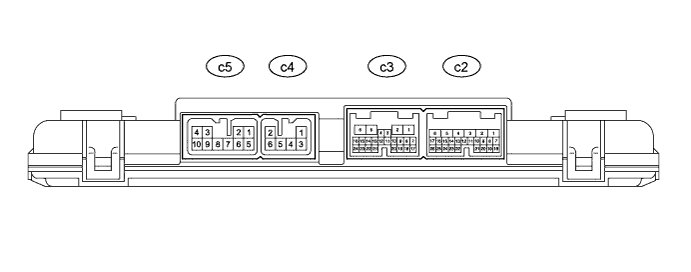
CHECK POSITION CONTROL ECU ASSEMBLY (for Front Passenger Side, Luxury Seat Type)
-
Disconnect the c2 and c3 position control ECU assembly connectors.
-
Measure the voltage and resistance according to the value(s) in the table below.
Terminal No. (Symbol) Wiring Color Terminal Description Condition Specified Condition c2-1 (GND2) - Body ground B - Body ground Ground Always Below 1 Ω c2-2 (GND) - Body ground B - Body ground Ground Always Below 1 Ω c3-1 (+B2) - c2-2 (GND) Y - B Power source Always 11 to 14 V c3-2 (+B) - c2-2 (GND) G - B Power source Always 11 to 14 V c2-18 (SYSB) - c2-2 (GND) B - B System power source Always 11 to 14 V If the result is not as specified, there may be a malfunction on the wire harness side.
-
Reconnect the c2 and c3 connectors to the position control ECU assembly.
-
Measure the voltage and resistance according to the value(s) in the table below.
Terminal No. (Symbol) Wiring Color Terminal Description Condition Specified Condition c5-6 (SLD+) - c2-2 (GND) Y - B Sliding motor signal (Forward) Slide switch off Below 1 V Slide switch on (Forward) 11 to 14 V c5-3 (SLD-) - c2-2 (GND) L - B Sliding motor signal (Backward) Slide switch off Below 1 V Slide switch on (Backward) 11 to 14 V c5-4 (FRV-) - c2-2 (GND) V - B Front vertical motor signal (Downward) Front vertical switch off Below 1 V Front vertical switch on (Downward) 11 to 14 V c5-7 (FRV+) - c2-2 (GND) LG - B Front vertical motor signal (Upward) Front vertical switch off Below 1 V Front vertical switch on (Upward) 11 to 14 V c5-8 (RCL+) - c2-2 (GND) P - B Reclining motor signal (Forward) Reclining switch off Below 1 V Reclining switch on (Forward) 11 to 14 V c5-10 (RCL-) - c2-2 (GND) GR - B Reclining motor signal (Backward) Reclining switch off Below 1 V Reclining switch on (Backward) 11 to 14 V c5-2 (LFT+) - c2-2 (GND) B - B Lifter motor signal (Upward) Lifter switch off Below 1 V Lifter switch on (Upward) 11 to 14 V c5-9 (LFT-) - c2-2 (GND) BE - B Lifter motor signal (Downward) Lifter switch off Below 1 V Lifter switch on (Downward) 11 to 14 V c3-5 (L+) - c2-2 (GND) V - B Lumbar motor signal (Forward) Lumbar switch off Below 1 V Lumbar switch on (Forward) 11 to 14 V c2-3 (L-) - c2-2 (GND) BE - B Lumbar motor signal (Backward) Lumbar switch off Below 1 V Lumbar switch on (Backward) 11 to 14 V c4-4 (PEL+) - c2-2 (GND) G - B Pelvis motor signal (Forward) Pelvis switch off Below 1 V Pelvis switch on (Forward) 11 to 14 V c4-2 (PEL-) - c2-2 (GND) R - B Pelvis motor signal (Backward) Pelvis switch off Below 1 V Pelvis switch on (Backward) 11 to 14 V c4-1 (MR+) - c2-2 (GND) W - B Front seat back adjuster motor signal (Forward) Front seat back adjuster switch off Below 1 V Front seat back adjuster switch on (Forward) 11 to 14 V c4-5 (MR-) - c2-2 (GND) L - B Front seat back adjuster motor signal (Backward) Front seat back adjuster switch off Below 1 V Front seat back adjuster switch on (Backward) 11 to 14 V c3-6 (C+) - c2-2 (GND) L - B Cushion motor signal (Forward)*1
Ottoman motor signal (Forward)*2
Cushion switch off*1
Ottoman switch off*2
Below 1 V Cushion switch on (Forward)*1
Ottoman switch on (Forward)*2
11 to 14 V c2-4 (C-) - c2-2 (GND) V - B Cushion motor signal (Backward)*1
Ottoman motor signal (Backward)*2
Cushion switch off*1
Ottoman switch off*2
Below 1 V Cushion switch on (Backward)*1
Ottoman switch on (Backward)*2
11 to 14 V c4-3 (ISR+) - c2-2 (GND) Y - B Side support motor signal (Paddle open) Side support switch off Below 1 V Side support switch on (Paddle open) 11 to 14 V c4-6 (ISR-) - c2-2 (GND) G - B Side support motor signal (Paddle close) Side support switch off Below 1 V Side support switch on (Paddle close) 11 to 14 V c2-20 (SGND) - c2-2 (GND) BR - B Position sensor ground Always Below 1 Ω c3-24 (SSFV) - c2-20 (SGND) P - BR Front vertical position signal Front vertical function operating 4.5 to 4.8 V c3-10 (SSRL) - c2-20 (SGND) R - BR Lifter position signal Lifter function operating 4.5 to 4.8 V c3-8 (SSRS) - c2-20 (SGND) SB - BR Slide position signal Slide function operating 4.5 to 4.8 V c3-14 (SSRR) - c2-20 (SGND) W - BR Reclining position signal Reclining function operating 4.5 to 4.8 V c3-13 (SSLB) - c2-20 (SGND) GR - BR Lumbar position signal Lumbar function operating 4.5 to 4.8 V c3-15 (SSPL) - c2-20 (SGND) LG - BR Pelvis position signal Pelvis function operating 4.5 to 4.8 V c3-9 (SSMR) - c2-20 (SGND) G - BR Front seat back adjuster position signal Front seat back adjuster function operating 4.5 to 4.8 V c3-3 (SSRC) - c2-20 (SGND) Y - BR Cushion position signal*1
Ottoman position signal*2
Cushion function operating*1
Ottoman function operating*2
4.5 to 4.8 V c3-16 (SSIR) - c2-20 (SGND) L - BR Side support position signal Side support function operating 4.5 to 4.8 V c2-25 (SWS1) - c3-18 (SWD1) B - Y Power seat switch signal Slide switch off (Forward) 11 to 14 V Slide switch on (Forward) Below 1 V c2-25 (SWS1) - c3-19 (SWD2) B - L Power seat switch signal Slide switch off (Backward) 11 to 14 V Slide switch on (Backward) Below 1 V c2-25 (SWS1) - c3-20 (SWD3) B - GR Power seat switch signal Reclining switch off (Forward) 11 to 14 V Reclining switch on (Forward) Below 1 V c2-25 (SWS1) - c3-11 (SWD4) B - V Power seat switch signal Reclining switch off (Backward) 11 to 14 V Reclining switch on (Backward) Below 1 V c2-25 (SWS1) - c3-21 (SWD5) B - SB Power seat switch signal Side support switch off (Paddle open) 11 to 14 V Side support switch on (Paddle open) Below 1 V c2-23 (SWS2) - c3-18 (SWD1) W - Y Power seat switch signal Lifter switch off (Upward) 11 to 14 V Lifter switch on (Upward) Below 1 V c2-23 (SWS2) - c3-19 (SWD2) W - L Power seat switch signal Lifter switch off (Downward) 11 to 14 V Lifter switch on (Downward) Below 1 V c2-23 (SWS2) - c3-20 (SWD3) W - GR Power seat switch signal Front vertical switch off (Downward) 11 to 14 V Front vertical switch on (Downward) Below 1 V c2-23 (SWS2) - c3-11 (SWD4) W - V Power seat switch signal Front vertical switch off (Upward) 11 to 14 V Front vertical switch on (Upward) Below 1 V c2-23 (SWS2) - c3-21 (SWD5) W - SB Power seat switch signal Side support switch off (Paddle close) 11 to 14 V Side support switch on (Paddle close) Below 1 V c2-16 (SWS3) - c3-18 (SWD1) R - Y Power seat switch signal Lumbar switch off (Forward) 11 to 14 V Lumbar switch on (Forward) Below 1 V c2-16 (SWS3) - c3-19 (SWD2) R - L Power seat switch signal Lumbar switch off (Backward) 11 to 14 V Lumbar switch on (Backward) Below 1 V c2-16 (SWS3) - c3-20 (SWD3) R - GR Power seat switch signal Pelvis switch off (Forward) 11 to 14 V Pelvis switch off (Forward) Below 1 V c2-16 (SWS3) - c3-11 (SWD4) R - V Power seat switch signal Pelvis switch off (Backward) 11 to 14 V Pelvis switch on (Backward) Below 1 V c2-14 (SWS4) - c3-18 (SWD1) G - Y Power seat switch signal Front seat back adjuster switch off (Forward) 11 to 14 V Front seat back adjuster switch on (Forward) Below 1 V c2-14 (SWS4) - c3-19 (SWD2) G - L Power seat switch signal Front seat back adjuster switch off (Backward) 11 to 14 V Front seat back adjuster switch on (Backward) Below 1 V c2-14 (SWS4) - c3-20 (SWD3) G - GR Power seat switch signal Cushion switch off (Forward)*1
Ottoman switch off (Forward)*2
11 to 14 V Cushion switch on (Forward)*1
Ottoman switch on (Forward)*2
Below 1 V c2-14 (SWS4) - c3-11 (SWD4) G - V Power seat switch signal Cushion switch off (Backward)*1
Ottoman switch off (Backward)*2
11 to 14 V Cushion switch on (Backward)*1
Ottoman switch on (Backward)*2
Below 1 V c2-17 (HRFS) - c2-2 (GND) L - B Power seat front switch signal Reclining switch on (Forward) 11 to 14 V Reclining switch off Below 1 V c2-21 (HRRS) - c2-2 (GND) G - B Power seat front switch signal Reclining switch on (Backward) 11 to 14 V Reclining switch off Below 1 V c2-24 (SLDF) - c2-2 (GND) V - B Power seat front switch signal Slide switch on (Forward) 11 to 14 V Slide switch off Below 1 V c2-26 (SLDR) - c2-2 (GND) W - B Power seat front switch signal Slide switch on (Backward) 11 to 14 V Slide switch off Below 1 V
-
*1: for Ottoman
-
*2: except Ottoman
-
-
-
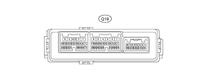
CHECK FRONT MULTIPLEX NETWORK DOOR ECU LH
-
Disconnect the Q19 front multiplex network door ECU LH connector.
-
Measure the voltage and resistance according to the value(s) in the table below.
Terminal No. (Symbol) Wiring Color Terminal Description Condition Specified Condition Q19-4 (CPUB) - Q19-1 (GND) P - W-B Power source Always 11 to 14 V Q19-6 (BDR) - Q19-1 (GND) V - W-B Power source Always 11 to 14 V Q19-3 (SIG) - Q19-1 (GND) B - W-B Power source (IG) Power switch on (IG) 11 to 14 V Q19-3 (SIG) - Q19-1 (GND) B - W-B Power source (IG) Power switch off Below 1 V Q19-1 (GND) - Body ground W-B - Body ground Ground Always Below 1 Ω If the result is not as specified, there may be a malfunction on the wire harness side.
-
Reconnect the Q19 connector to the front multiplex network door ECU LH.
-
Measure the voltage and waveform according to the value(s) in the table below.
Terminal No. (Symbol) Wiring Color Terminal Description Condition Specified Condition Q19-22 (M1) - Q19-26 (MSWE) B - P M1 switch signal Power switch on (IG), M1 switch off Pulse generation Power switch on (IG), M1 switch on Below 1 V Q19-23 (M2) - Q19-26 (MSWE) SB - P M2 switch signal Power switch on (IG), M2 switch off Pulse generation Power switch on (IG), M2 switch on Below 1 V Q19-24 (M3) - Q19-26 (MSWE) V - P M3 switch signal Power switch on (IG), M3 switch off Pulse generation Power switch on (IG), M3 switch on Below 1 V Q19-25 (MM) - Q19-26 (MSWE) LG - P SET switch signal Power switch on (IG), SET switch off Pulse generation Power switch on (IG), SET switch on Below 1 V
-
-
CHECK FRONT MULTIPLEX NETWORK DOOR ECU RH

-
Disconnect the Q4 front multiplex network door ECU RH connector.
-
Measure the voltage and resistance according to the value(s) in the table below.
Terminal No. (Symbol) Wiring Color Terminal Description Condition Specified Condition Q4-6 (BDR) - Q4-1 (GND) V - W-B Power source Always 11 to 14 V Q4-4 (CPUB) - Q4-1 (GND) P - W-B Power source Always 11 to 14 V Q4-3 (SIG) - Q4-1 (GND) B - W-B Power source Power switch on (IG) 11 to 14 V Q4-3 (SIG) - Q4-1 (GND) B - W-B Power source (IG) Power switch off Below 1 V Q4-1 (GND) - Body ground W-B - Body ground Ground Always Below 1 Ω If the result is not as specified, there may be a malfunction on the wire harness side.
-
Reconnect the Q4 connector to the front multiplex network door ECU RH.
-
Measure the voltage and waveform according to the value(s) in the table below.
Terminal No. (Symbol) Wiring Color Terminal Description Condition Specified Condition Q4-22 (M1) - Q4-26 (MSWE) B - P M1 switch signal Power switch on (IG), M1 switch off Pulse generation Power switch on (IG), M1 switch on Below 1 V Q4-23 (M2) - Q4-26 (MSWE) SB - P M2 switch signal Power switch on (IG), M2 switch off Pulse generation Power switch on (IG), M2 switch on Below 1 V Q4-24 (M3) - Q4-26 (MSWE) V - P M3 switch signal Power switch on (IG), M3 switch off Pulse generation Power switch on (IG), M3 switch on Below 1 V Q4-25 (MM) - Q4-26 (MSWE) LG - P SET switch signal Power switch on (IG), SET switch off Pulse generation Power switch on (IG), SET switch on Below 1 V
-
-
CHECK COWL SIDE JUNCTION BLOCK LH, MAIN BODY ECU (MULTIPLEX NETWORK BODY ECU)
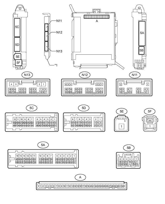
Text in Illustration *1 Main Body ECU (Multiplex Network Body ECU) - -
-
Remove the main body ECU (multiplex network body ECU) from the cowl side junction block LH Click here.
-
Connect the cowl side junction block LH connectors.
-
Measure the voltage and resistance according to the value(s) in the table below.
Tester Connection Wiring Color Terminal Description Condition Specified Condition A-32 (IG) - Body ground - Power source (IG) Power switch on (IG) 11 to 14 V A-30 (BECU) - Body ground - Power source Always 11 to 14 V A-11 (GND1) - Body ground - Ground Always Below 1 Ω -
Install the main body ECU (multiplex network body ECU) Click here.
-
Measure the voltage and waveform according to the value(s) in the table below.
Tester Connection Wiring Color Terminal Description Condition Specified Condition 5C-44 (FLCY) - Body ground R - Body ground Front door courtesy light switch assembly signal Driver door closed Pulse generation Driver door open Below 1 V N13-9 (CANP) R CAN communication signal - - N13-10 (CANN) GR CAN communication signal - -
-