PRE-CRASH SAFETY SYSTEM Pre-crash Safety System Cancel Switch Circuit
DESCRIPTION
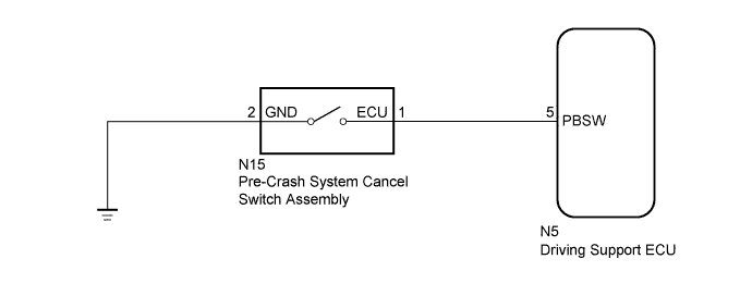
The driving support ECU receives pre-crash safety cancel on/off signals from the pre-crash system cancel switch assembly.
WIRING DIAGRAM
INSPECTION PROCEDURE
Note
When replacing the driving support ECU, always replace it with a new one and be sure to perform initialization Click here. If an ECU which was installed to another vehicle is used, the information stored in the ECU will not match the information from the vehicle, and as a result, a DTC may be stored.
PROCEDURE
-
READ VALUE USING GTS (PCS BRAKE OFF SWITCH)
-
Use the Data List to check if the pre-crash safety system cancel switch assembly is functioning properly Click here.
Pre-Crash 2 Tester Display Measurement Item/Range Normal Condition Diagnostic Note PCS Brake OFF Switch Pre-crash system cancel switch assembly signal / ON or OFF ON: Pre-crash system cancel switch assembly on
OFF: Pre-crash system cancel switch assembly off
- OK On screen, each item changes between ON and OFF according to above chart.
NG 
INSPECT PRE-CRASH SYSTEM CANCEL SWITCH ASSEMBLY Click here
OK 
PROCEED TO NEXT SUSPECTED AREA SHOWN IN PROBLEM SYMPTOMS TABLE Click here
-
-
INSPECT PRE-CRASH SYSTEM CANCEL SWITCH ASSEMBLY
-
Remove the pre-crash system cancel switch assembly Click here.
-
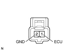
Measure the resistance according to the value(s) in the table below.
Standard Resistance Tester Connection Switch Condition Specified Condition 1 (ECU) - 2 (GND) Pressed Below 1 Ω Not pressed 10 kΩ or higher
NG 
REPLACE PRE-CRASH SAFETY SYSTEM CANCEL SWITCH ASSEMBLY Click here
OK 
-
-
CHECK HARNESS AND CONNECTOR (PRE-CRASH SYSTEM CANCEL SWITCH ASSEMBLY - DRIVING SUPPORT ECU AND BODY GROUND)
-
Disconnect the N15 pre-crash system cancel switch assembly connector.
-
Disconnect the N5 driving support ECU connector.
-
Measure the resistance according to the value(s) in the table below.
Standard Resistance Tester Connection Condition Specified Condition N15-1 (ECU) - N5-5 (PBSW) Always Below 1 Ω N15-2 (GND) - Body ground N15-1 (ECU) - Body ground Always 10 kΩ or higher
NG
REPAIR OR REPLACE HARNESS OR CONNECTOR
OK
REPLACE DRIVING SUPPORT ECU Click here
-