PRE-CRASH SAFETY SYSTEM TERMINALS OF ECU

-
CHECK SEAT BELT CONTROL ECU
-
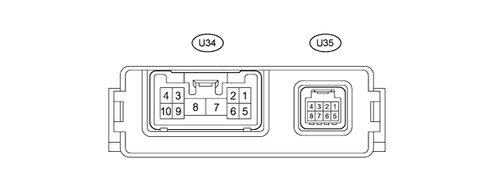
Disconnect the U34 and U35 seat belt control ECU connectors.
-
Measure the resistance and voltage according to the value(s) in the table below.
Terminal No. (Symbol) Wiring Color Terminal Description Condition Specified Condition U34-7 (+B) - Body ground R - Body ground Power supply Always 11 to 14 V U34-8 (PGND) - Body ground W-B - Body ground Body ground Always Below 1 Ω U35-8 (IG1) - Body ground G - Body ground Seat belt control ECU power supply Power switch on (IG) 11 to 14 V U35-8 (IG1) - Body ground G - Body ground Seat belt control ECU power supply Power switch off Below 1 V If the result is not as specified, there may be a malfunction on the wire harness side.
-
Reconnect the U34 and U35 seat belt control ECU connectors.
-
Measure the voltage according to the value(s) in the table below.
Terminal No. (Symbol) Wiring Color Terminal Description Condition Specified Condition U34-2 (MOR+) - U34-1 (MOR-) B - LG Seat belt motor RH power supply Power switch on (IG) 4.0 to 8.5 V U34-2 (MOR+) - U34-1 (MOR-) B - LG Seat belt motor RH power supply Power switch off Below 1 V U34-3 (MOL+) - U34-4 (MOL-) L - W Seat belt motor LH power supply Power switch on (IG) 4.0 to 8.5 V U34-3 (MOL+) - U34-4 (MOL-) L - W Seat belt motor LH power supply Power switch off Below 1 V U35-5 (PBK+) - U35-6 (PBK-) G - L Front passenger buckle switch line Power switch on (IG), Front passenger seat inner belt tongue plate not inserted → inserted Pulse generation
(See waveform 1)
-
Using an oscilloscope, check waveform 1.
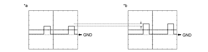
Text in Illustration *a Tongue plate inserted *b Tongue plate not inserted Measurement Condition Item Content Tester Connection U35-5 (PBK+) - U35-6 (PBK-) Tool Setting 2 V/DIV., 500 μs/DIV. Vehicle Condition Power switch on (IG), passenger seat inner belt tongue plate not inserted → inserted
-
-
CHECK DRIVING SUPPORT ECU
-
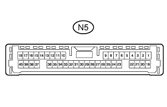
Disconnect the N5 driving support ECU connector.
Note
If a load of more than 10 kg (22 lb.) is placed on the connector, it may break. Do not place more load than is necessary on the connector.
-
Measure the voltage and resistance according to the value(s) in the table below.
Terminal No. (Symbol) Wiring Color Terminal Description Condition Specified Condition N5-2 (CA3H) - Body ground G - Body ground CAN communication system Power switch on (IG) Pulse generation
(See waveform 1)
N5-5 (PBSW) - Body ground L - Body ground Pre-crash system cancel switch signal Pre-crash system cancel switch on Below 1 Ω N5-5 (PBSW) - Body ground L - Body ground Pre-crash system cancel switch signal Pre-crash system cancel switch off 10 kΩ or higher N5-17 (CA2L) - Body ground LG - Body ground CAN communication system Power switch on (IG) Pulse generation
(See waveform 2)
N5-18 (CA1N) - Body ground W - Body ground CAN communication system Power switch on (IG) Pulse generation
(See waveform 2)
N5-20 (CA3L) - Body ground SB - Body ground CAN communication system Power switch on (IG) Pulse generation
(See waveform 2)
N5-25 (GND) - Body ground BR - Body ground*1
W-B - Body ground*2
Body ground Always Below 1 Ω N5-27 (STP-) - Body ground R - Body ground Stop light switch signal input Brake pedal depress 11 to 14 V N5-27 (STP-) - Body ground R - Body ground Stop light switch signal input Brake pedal release Below 1 V N5-28 (ST1-) - Body ground GR - Body ground Stop light switch signal input Power switch on (IG),
brake pedal release
11 to 14 V N5-28 (ST1-) - Body ground GR - Body ground Stop light switch signal input Power switch on (IG),
brake pedal depress
Below 1 V N5-30 (B) - Body ground L - Body ground Power supply Power switch on (IG) 11 to 14 V N5-30 (B) - Body ground L - Body ground Power supply Power switch off Below 1 V N5-39 (CA2H) - Body ground V - Body ground CAN communication system Power switch on (IG) Pulse generation
(See waveform 1)
N5-40 (CA1P) - Body ground G - Body ground CAN communication system Power switch on (IG) Pulse generation
(See waveform 1)
-
*1: for LHD
-
*2: for RHD
If the result is not as specified, there may be a malfunction on the wire harness side.
-
-

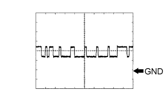
Using an oscilloscope, check waveform 1.
Measurement Condition Item Content Tester Connection
-
N5-2 (CA3H) - Body ground
-
N5-39 (CA2H) - Body ground
-
N5-40 (CA1P) - Body ground
Tool Setting 1 V/DIV., 10 μs/DIV. Vehicle Condition Power switch on (IG) -
-
Using an oscilloscope, check waveform 2.
Measurement Condition Item Content Tester Connection
-
N5-17 (CA2L) - Body ground
-
N5-18 (CA1N) - Body ground
-
N5-20 (CA3L) - Body ground
Tool Setting 1 V/DIV., 10 μs/DIV. Vehicle Condition Power switch on (IG) -
-
-
CHECK DRIVER MONITOR ECU ASSEMBLY (W/ DRIVER MONITOR CAMERA)
-
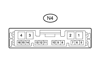
Disconnect the N4 driver monitor ECU assembly connector.
-
Measure the resistance and voltage according to the value(s) in the table below.
Terminal No. (Symbol) Wiring Color Terminal Description Condition Specified Condition N4-1 (IG) - N4-2 (GND) LG - W-B Camera power supply Power switch on (IG) 11 to 14 V N4-1 (IG) - N4-2 (GND) LG - W-B Camera power supply Power switch off Below 1 V N4-2 (GND) - Body ground W-B - Body ground Body ground Always Below 1 V N4-16 (CGND) - Body ground B - Body ground Camera ground Always Below 1 Ω If the result is not as specified, there may be a malfunction on the wire harness side.
-
Reconnect the N4 driver monitor ECU assembly connector.
-
Measure the voltage according to the value(s) in the table below.
Terminal No. (Symbol) Wiring Color Terminal Description Condition Specified Condition N4-11 (CANL) - Body ground W - Body ground CAN communication system Power switch on (IG) Pulse generation
(See waveform 1)
N4-12 (CANH) - Body ground R - Body ground CAN communication system Power switch on (IG) Pulse generation
(See waveform 2)
N4-13 (CB+) - Body ground W - Body ground Camera power supply Power switch on (IG) 5.5 to 6.5 V N4-13 (CB+) - Body ground W - Body ground Camera power supply Power switch off Below 1 V N4-14 (CV+) - N4-15 (CV-) R - Shielded Camera output Power switch on (IG) Pulse generation -

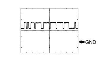
Using an oscilloscope, check waveform 1.
Measurement Condition Item Content Tester Connection N4-11 (CANL) - Body ground Tool Setting 1 V/DIV., 10 μs/DIV. Vehicle Condition Power switch on (IG) -
Using an oscilloscope, check waveform 2.
Measurement Condition Item Content Tester Connection N4-12 (CANH) - Body ground Tool Setting 1 V/DIV., 10 μs/DIV. Vehicle Condition Power switch on (IG)
-