AIR CONDITIONING SYSTEM, Diagnostic DTC:B1473/73

| DTC Code | DTC Name |
|---|---|
| B1473/73 | A/C Inverter Start-up Signal System Malfunction |
DESCRIPTION
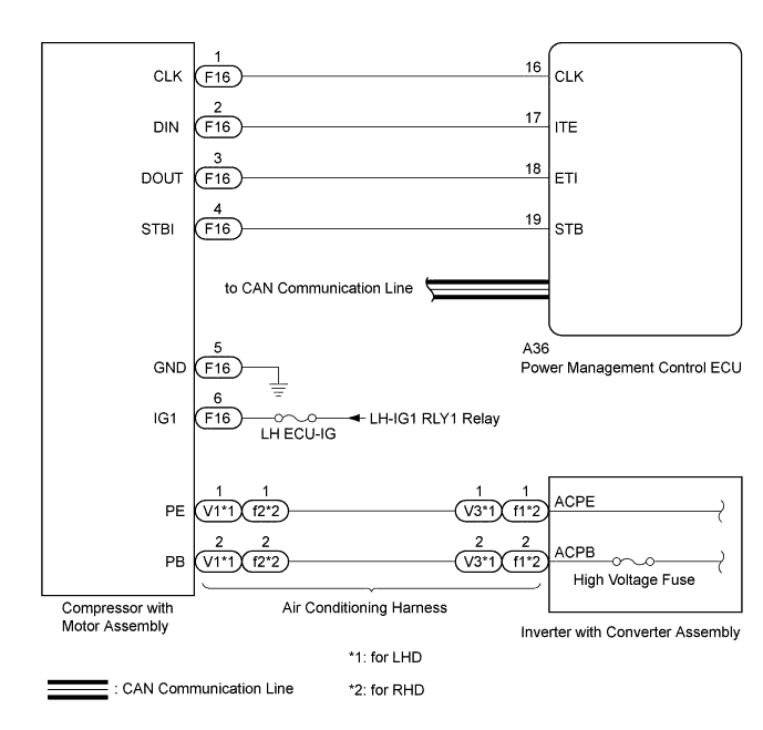
The inverter activation signal is sent to the compressor with motor assembly from the power management control ECU. Compressor control is stopped and the DTC is stored if there is an open or short in the signal circuit.
| DTC Code | DTC Detection Condition | Trouble Area |
|---|---|---|
| B1473/73 | Open or short in compressor with motor assembly start-up signal system. |
|
WIRING DIAGRAM
INSPECTION PROCEDURE
Note
-
Inspect the fuses for circuits related to this system before performing the following inspection procedure.
-
The hybrid control system and air conditioning system output DTCs separately. Inspect DTCs following the diagnosis procedure for the hybrid control system first if any DTCs from those systems are output simultaneously Click here.
-
If DTC B1498 is output at the same time, troubleshoot DTC B1498 first.
PROCEDURE
-
CHECK CAN COMMUNICATION SYSTEM
-
Use the GTS to check if the CAN communication system is functioning normally.
-
for LHD: Click here.
-
for RHD: Click here.
Result Result Proceed to CAN DTC is not output A CAN DTC is output (for LHD) B CAN DTC is output (for RHD) C -
B 
GO TO CAN COMMUNICATION SYSTEM Click here
C
GO TO CAN COMMUNICATION SYSTEM Click here
A 
-
-
CHECK HYBRID CONTROL SYSTEM
-
Check if DTCs for the hybrid control system are output using the GTS Click here.
Result Result Proceed to Hybrid control system DTC is not output A Hybrid control system DTC is output B
B
GO TO HYBRID CONTROL SYSTEM Click here
A
-
-
CHECK HARNESS AND CONNECTOR (POWER MANAGEMENT CONTROL ECU - COMPRESSOR WITH MOTOR ASSEMBLY)
CAUTION:
Do not disconnect the connector on the high voltage side.
-
Disconnect the A36 power management control ECU connector.
-
Disconnect the F16 compressor with motor assembly connector.
-
Measure the resistance according to the value(s) in the table below.
Standard Resistance Tester Connection Condition Specified Condition A36-19 (STB) - F16-4 (STBI) Always Below 1 Ω A36-19 (STB) - Body ground Always 10 kΩ or higher
NG
REPAIR OR REPLACE HARNESS OR CONNECTOR
OK
-
-
CHECK COMPRESSOR WITH MOTOR ASSEMBLY
-
Reconnect the F16 compressor with motor assembly connector.
-
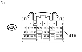
Text in Illustration *a Front view of wire harness connector
(to Power Management Control ECU)
Measure the voltage according to the value(s) in the table below.
Standard Voltage Tester Connection Switch Condition Specified Condition A36-19 (STB) - Body ground Power switch on (IG) 11 to 14 V A36-19 (STB) - Body ground Power switch off Below 1 V
NG
REPLACE COMPRESSOR WITH MOTOR ASSEMBLY Click here
OK 
REPLACE POWER MANAGEMENT CONTROL ECU Click here
-