AIR CONDITIONING SYSTEM, Diagnostic DTC:B1461/61

| DTC Code | DTC Name |
|---|---|
| B1461/61 | Emission Gas NOx Sensor Circuit |
DESCRIPTION
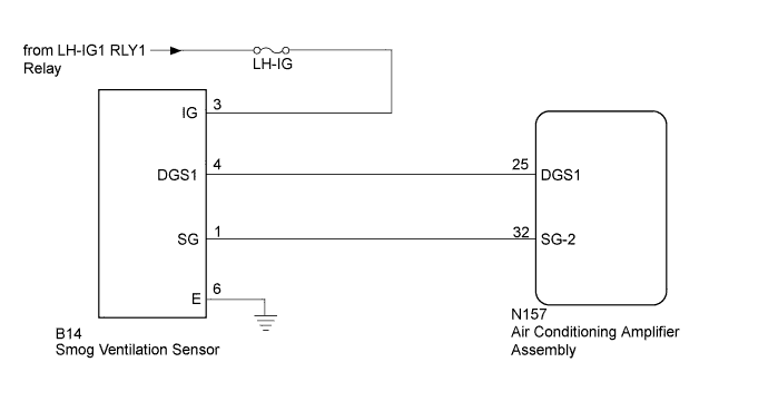
The smog ventilation sensor is installed to the front of the cooler condenser assembly and is used to control automatic switching between recirculation and fresh air modes. The smog ventilation sensor detects components of the exhaust gas (NOx) and transmits a signal to the air conditioning amplifier assembly.
| DTC Code | DTC Detection Condition | Trouble Area |
|---|---|---|
| B1461/61 | Short in smog ventilation sensor circuit (NOx) |
|
WIRING DIAGRAM
INSPECTION PROCEDURE
Note
-
Inspect the fuses for circuits related to this system before performing the following inspection procedure.
-
When the auxiliary battery is disconnected or the air conditioning amplifier assembly is replaced, be sure to perform servo motor initialization Click here.
-
Before disconnecting the cable form the negative (-) battery terminal or replacing the air conditioning amplifier assembly, record the last operation state of the air conditioning for each transmitter. After replacement, it is necessary to perform memory registration for each transmitter Click here.
PROCEDURE
-
READ VALUE USING GTS (EMISSION GAS NOX SENSOR)
-
Connect the GTS to the DLC3.
-
Turn the power switch on (IG).
-
Turn the GTS on.
-
Enter the following menus: Body Electrical / Air Conditioner / Data List Click here.
-
Check the value(s) by referring to the table below.
Air Conditioner Tester Display Measurement Item/Range Normal Condition Diagnostic Note Emission Gas Nox Sensor Smog ventilation sensor /
Min.: 0, Max.: 255
Displays concentration of exhaust gas (NOx) around smog ventilation sensor (increases when concentration of exhaust gas increases) - OK The display is as specified in the normal condition column. Result Result Proceed to NG A OK (When troubleshooting according to Problem Symptoms Table) B OK (When troubleshooting according to the DTC) C
B 
PROCEED TO NEXT SUSPECTED AREA SHOWN IN PROBLEM SYMPTOMS TABLE Click here
C
REPLACE AIR CONDITIONING AMPLIFIER ASSEMBLY Click here
A 
-
-
CHECK HARNESS AND CONNECTOR (SMOG VENTILATION SENSOR - BATTERY AND BODY GROUND)
-
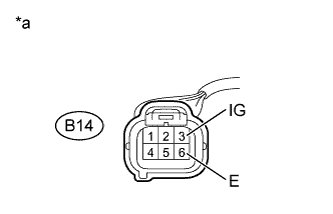
Text in Illustration *a Front view of wire harness connector
(to Smog Ventilation Sensor)
Disconnect the smog ventilation sensor connector.
-
Measure the voltage according to the value(s) in the table below.
Standard Voltage Tester Connection Switch Condition Specified Condition B14-3 (IG) - Body ground Power switch on (IG) 11 to 14 V B14-3 (IG) - Body ground Power switch off Below 1 V -
Measure the resistance according to the value(s) in the table below.
Standard Resistance Tester Connection Condition Specified Condition B14-6 (E) - Body ground Always Below 1 Ω
NG
REPAIR OR REPLACE HARNESS OR CONNECTOR
OK
-
-
CHECK HARNESS AND CONNECTOR (SMOG VENTILATION SENSOR - AIR CONDITIONING AMPLIFIER ASSEMBLY)
-
Disconnect the N157 air conditioning amplifier assembly connector.
-
Measure the resistance according to the value(s) in the table below.
Standard Resistance Tester Connection Condition Specified Condition B14-1 (SG) - N157-32 (SG-2) Always Below 1 Ω B14-4 (DGS1) - N157-25 (DGS1) Always Below 1 Ω B14-1 (SG) - Body ground Always 10 kΩ or higher B14-4 (DGS1) - Body ground Always 10 kΩ or higher B14-1 (SG) - B14-4 (DGS1) Always 10 kΩ or higher
NG
REPAIR OR REPLACE HARNESS OR CONNECTOR
OK
-
-
INSPECT SMOG VENTILATION SENSOR
-
Remove the smog ventilation sensor Click here.
-
Inspect the smog ventilation sensor Click here.
NG
REPLACE SMOG VENTILATION SENSOR Click here
OK 
REPLACE AIR CONDITIONING AMPLIFIER ASSEMBLY Click here
-