AIR CONDITIONING SYSTEM, Diagnostic DTC:B1442/42

| DTC Code | DTC Name |
|---|---|
| B1442/42 | Air Inlet Damper Control Servo Motor Circuit |
DESCRIPTION
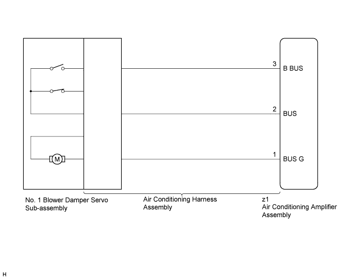
The No. 1 blower damper servo sub-assembly sends pulse signals to inform the air conditioning amplifier assembly of the damper position. The air conditioning amplifier assembly activates the motor (normal, reverse) based on the signals to move the air inlet mode selection No. 1 blower damper servo sub-assembly to any position, which controls the intake air settings (FRESH, FRESH/RECIRCULATION, and RECIRCULATION).
The air conditioning amplifier assembly communicates with the servo through a communication/driver IC and wiring assembly called the air conditioning harness assembly.
| DTC Code | DTC Detection Condition | Trouble Area |
|---|---|---|
| B1442/42 | Air inlet damper position sensor value does not change even if air conditioning amplifier assembly operates No. 1 blower damper servo sub-assembly |
|
WIRING DIAGRAM
INSPECTION PROCEDURE
Note
-
Confirm that no mechanical problem is present because this diagnostic code can be output when either a damper link or the damper is mechanically locked.
-
When the auxiliary battery is disconnected, or a servo motor or the air conditioning amplifier assembly is replaced, be sure to perform servo motor initialization Click here.
-
Before disconnecting the cable form the negative (-) battery terminal or replacing the air conditioning amplifier assembly, record the last operation state of the air conditioning for each transmitter. After replacement, it is necessary to perform memory registration for each transmitter Click here.
PROCEDURE
-
CHECK FOR DTC
-
Clear the DTCs Click here.
-
Check for DTCs Click here.
Result Result Proceed to DTC B1442/42 is not output A DTC B1442/42 is output B DTC B1442/42 and B1497/97 are output C
B 
READ VALUE USING GTS (AIR INLET DAMPER ACTUAL PULSE) Click here
C 
GO TO DTC B1497/97 Click here
A 
USE SIMULATION METHOD TO CHECK Click here
-
-
READ VALUE USING GTS (AIR INLET DAMPER ACTUAL PULSE)
-
Connect the GTS to the DLC3.
-
Turn the power switch on (IG).
-
Turn the GTS on.
-
Enter the following menus: Body Electrical / Air Conditioner / Data List Click here.
-
Check the value(s) by referring to the table below.
Air Conditioner Tester Display Measurement Item/Range Normal Condition Diagnostic Note Air Inlet Damper Actual Pulse No. 1 blower damper servo sub-assembly actual pulse /
Min.: 128, Max.: 383
-
FRESH: 206 (pulse)
-
RECIRCULATION: 238 (pulse)
for LHD:
-
FRESH: 306 (pulse)
-
RECIRCULATION: 274 (pulse)
for RHD:
- OK The display is as specified in the normal condition column. Result Result Proceed to NG A OK (When troubleshooting according to Problem Symptoms Table) B OK (When troubleshooting according to the DTC) C -
B
PROCEED TO NEXT SUSPECTED AREA SHOWN IN PROBLEM SYMPTOMS TABLE Click here
C
REPLACE AIR CONDITIONING AMPLIFIER ASSEMBLY Click here
A 
-
-
PERFORM ACTIVE TEST USING GTS (AIR INLET DAMPER TARG PULSE)
-
Connect the GTS to the DLC3.
-
Turn the power switch on (IG).
-
Turn the GTS on.
-
Enter the following menus: Body Electrical / Air Conditioner / Active Test Click here.
-
Check the operation by referring to the table below.
Air Conditioner Tester Display Test Part Control Range Diagnostic Note Air Inlet Damper Targ Pulse No. 1 blower damper servo sub-assembly pulse Min.: 128, Max.: 383 Operates between 206 to 238 pulses*1
Operates between 274 to 306 pulses*2
-
*1: for LHD
-
*2: for RHD
OK The No. 1 blower damper servo sub-assembly pulse signal changes according to the target pulse specified by the Active Test. -
NG
CHECK NO. 1 BLOWER DAMPER SERVO SUB-ASSEMBLY Click here
OK
REPLACE AIR CONDITIONING AMPLIFIER ASSEMBLY Click here
-
-
CHECK NO. 1 BLOWER DAMPER SERVO SUB-ASSEMBLY
-
Replace the No. 1 blower damper servo sub-assembly Click here.
Tech Tips
Since the servo motor cannot be inspected while it is removed from the vehicle, replace the servo motor with a new or known good one and check that the condition returns to normal.
-
Check for DTCs Click here.
OK DTC B1442/42 is not output.
NG
CHECK AIR CONDITIONING HARNESS ASSEMBLY Click here
OK
END (NO. 1 BLOWER DAMPER SERVO SUB-ASSEMBLY WAS DEFECTIVE)
-
-
CHECK AIR CONDITIONING HARNESS ASSEMBLY
-
Replace the air conditioning harness assembly Click here.
Tech Tips
Since the air conditioning harness assembly cannot be inspected while it is removed from the vehicle, replace the air conditioning harness assembly with a new or known good one and check that the condition returns to normal.
-
Check for DTCs Click here.
OK DTC B1442/42 is not output.
NG
REPLACE AIR CONDITIONING AMPLIFIER ASSEMBLY Click here
OK
END (AIR CONDITIONING HARNESS ASSEMBLY WAS DEFECTIVE)
-