AIR CONDITIONING SYSTEM, Diagnostic DTC:B14A2

| DTC Code | DTC Name |
|---|---|
| B14A2 | Driver Side Solar Sensor Short Circuit |
DESCRIPTION
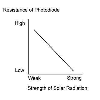
The automatic light control sensor is installed on the upper side of the instrument panel. It detects sunlight to control air conditioning AUTO mode. The output voltage from the automatic light control sensor varies in accordance with the amount of sunlight. When the sunlight increases, the output voltage increases. As the sunlight decreases, the output voltage decreases. The air conditioning amplifier assembly detects changes in the output voltage from the automatic light control sensor.
| DTC Code | DTC Detection Condition | Trouble Area |
|---|---|---|
| B14A2 | Short in driver side automatic light control sensor circuit |
|
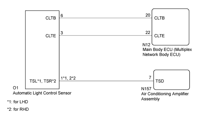
WIRING DIAGRAM
INSPECTION PROCEDURE
Note
-
When the auxiliary battery is disconnected or the air conditioning amplifier assembly is replaced, be sure to perform servo motor initialization Click here.
-
If the main body ECU (multiplex network body ECU) is replaced, refer to Service Bulletin.
-
Before disconnecting the cable form the negative (-) battery terminal or replacing the air conditioning amplifier assembly, record the last operation state of the air conditioning for each transmitter. After replacement, it is necessary to perform memory registration for each transmitter Click here.
PROCEDURE
-
READ VALUE USING GTS (SOLAR SENSOR [D SIDE])
-
Connect the GTS to the DLC3.
-
Turn the power switch on (IG).
-
Turn the GTS on.
-
Enter the following menus: Body Electrical / Air Conditioner / Data List Click here.
-
Check the value(s) by referring to the table below.
Air Conditioner Tester Display Measurement Item/Range Normal Condition Diagnostic Note Solar Sensor (D Side) Driver side automatic light control sensor /
Min.: 0, Max.: 255
Driver side automatic light control sensor value increases as brightness increases - OK The display is as specified in the Normal Condition column. Result Result Proceed to NG A OK (When troubleshooting according to Problem Symptoms Table) B OK (When troubleshooting according to the DTC) C
B 
PROCEED TO NEXT SUSPECTED AREA SHOWN IN PROBLEM SYMPTOMS TABLE Click here
C
REPLACE AIR CONDITIONING AMPLIFIER ASSEMBLY Click here
A 
-
-
CHECK HARNESS AND CONNECTOR (POWER SOURCE CIRCUIT)
-
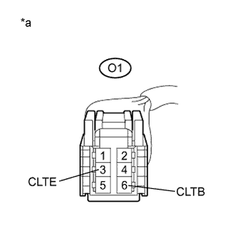
Text in Illustration *a Front view of wire harness connector
(to Automatic Light Control Sensor)
Disconnect the automatic light control sensor connector.
-
Measure the voltage according to the value(s) in the table below.
Standard Voltage Tester Connection Switch Condition Specified Condition O1-6 (CLTB) - O1-3 (CLTE) Power switch off Below 1 V O1-6 (CLTB) - O1-3 (CLTE) Power switch on (IG) 11 to 14 V
NG 
CHECK HARNESS AND CONNECTOR (MAIN BODY ECU (MULTIPLEX NETWORK BODY ECU) - AUTOMATIC LIGHT CONTROL SENSOR) Click here
OK
-
-
CHECK HARNESS AND CONNECTOR (AUTOMATIC LIGHT CONTROL SENSOR - AIR CONDITIONING AMPLIFIER ASSEMBLY)
-
Disconnect the N157 air conditioning amplifier assembly connector.
-
Measure the resistance according to the value(s) in the table below.
Standard Resistance for LHD Tester Connection Condition Specified Condition N157-7 (TSD) - O1-1 (TSL) Always Below 1 Ω N157-7 (TSD) - Body ground Always 10 kΩ or higher for RHD Tester Connection Condition Specified Condition N157-7 (TSD) - O1-2 (TSR) Always Below 1 Ω N157-7 (TSD) - Body ground Always 10 kΩ or higher
NG
REPAIR OR REPLACE HARNESS OR CONNECTOR
OK
-
-
INSPECT SOLAR SENSOR (AUTOMATIC LIGHT CONTROL SENSOR)
-
Inspect the automatic light control sensor. Refer to on-vehicle inspection procedure Click here.
NG
REPLACE AUTOMATIC LIGHT CONTROL SENSOR Click here
OK 
REPLACE AIR CONDITIONING AMPLIFIER ASSEMBLY Click here
-
-
CHECK HARNESS AND CONNECTOR (MAIN BODY ECU (MULTIPLEX NETWORK BODY ECU) - AUTOMATIC LIGHT CONTROL SENSOR)
-
Disconnect the N12 main body ECU (multiplex network body ECU) connector.
-
Disconnect the O1 automatic light control sensor connector.
-
Measure the resistance according to the value(s) in the table below.
Standard Resistance Tester Connection Condition Specified Condition N12-20 (CLTB) - O1-6 (CLTB) Always Blow 1 Ω N12-22 (CLTE) - O1-3 (CLTE) Always Blow 1 Ω N12-20 (CLTB) - Body ground Always 10 kΩ or higher N12-22 (CLTE) - Body ground Always 10 kΩ or higher N12-20 (CLTB) - N12-22 (CLTE) Always 10 kΩ or higher
NG
REPAIR OR REPLACE HARNESS OR CONNECTOR
OK
REPLACE MAIN BODY ECU (MULTIPLEX NETWORK BODY ECU) Click here
-