INJECTOR DRIVER INSTALLATION

-
INSTALL INJECTOR DRIVER
Note
Be careful not to drop or strike the injector driver.
-
Install the injector driver to the intake manifold with the 2 bolts and 2 nuts.
- Torque:
- 10 N*m { 102 kgf*cm, 7 ft.*lbf }
-
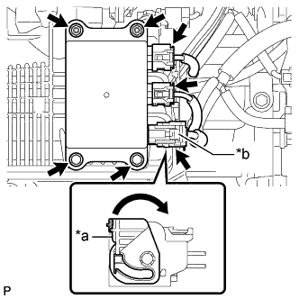
Text in Illustration *a Lock Lever *b Connector (with Lock) Connect the 2 injector driver connectors.
-
Connect the connector (with lock) to the injector driver and move the lock lever as shown in the illustration to engage the lock.
Note
Securely connect the connector (with lock) to the injector driver and engage the lock lever.
-
-
INSTALL NO. 1 INVERTER RESERVE TANK BRACKET (for LHD)
-
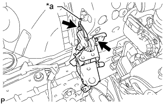
Text in Illustration *a Claw Install the No. 1 inverter reserve tank bracket with the 2 bolts.
- Torque:
- 8.5 N*m { 87 kgf*cm, 75 in.*lbf }
Tech Tips
Insert the claw of the No. 1 inverter reserve tank bracket into the hole of the body as shown in the illustration.
-
Attach the 2 wire harness clamps to the No. 1 inverter reserve tank bracket.
-
Connect the No. 3 engine wire to the No. 1 inverter reserve tank bracket with the bolt.
- Torque:
- 8.5 N*m { 87 kgf*cm, 75 in.*lbf }
-
-
CONNECT INVERTER RESERVE TANK ASSEMBLY (for LHD)
-
Connect the inverter reserve tank assembly to the No. 1 inverter reserve tank bracket with the 2 bolts.
- Torque:
- 13 N*m { 127 kgf*cm, 9 ft.*lbf }
-
Attach the clamp to connect the No. 3 inverter cooling hose to the No. 1 inverter reserve tank bracket.
-
Attach the clamp to connect the inlet hybrid water pump hose to the No. 1 inverter reserve tank bracket.
-
Attach the clamp to connect the wire harness to the inverter reserve tank assembly.
-
-
INSTALL AIR CLEANER CASE SUB-ASSEMBLY (for LHD)
-
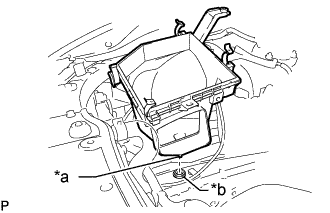
Text in Illustration *a Pin *b Air Cleaner Support Insert the pin of the air cleaner case sub-assembly into the hole of the air cleaner support as shown in the illustration.
-
Install the 2 bolts.
- Torque:
- 5.0 N*m { 51 kgf*cm, 44 in.*lbf }
-
Connect the wire harness clamp to the air cleaner case sub-assembly.
-
-
INSTALL AIR CLEANER FILTER ELEMENT SUB-ASSEMBLY (for LHD)
-
Install the air cleaner filter element sub-assembly to the air cleaner case sub-assembly.
-
-
INSTALL INLET NO. 1 AIR CLEANER (for LHD)
-
Install the No. 1 air cleaner inlet with the bolt.
- Torque:
- 5.0 N*m { 51 kgf*cm, 44 in.*lbf }
-
-
INSTALL COOL AIR INTAKE DUCT SEAL (for LHD)
-
INSTALL AIR CLEANER HOSE ASSEMBLY
-
CONNECT CABLE TO AUXILIARY BATTERY NEGATIVE TERMINAL
Note
When disconnecting the cable, some systems need to be initialized after the cable is reconnected Click here.