CYLINDER HEAD GASKET REMOVAL

-
REMOVE TIMING CHAIN COVER SUB-ASSEMBLY
-
SET NO. 1 CYLINDER TO TDC/COMPRESSION
-
Temporarily install the pulley set bolt.
-
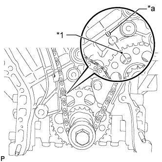
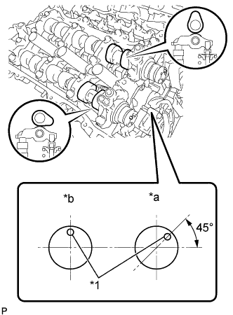
Text in Illustration *1 Timing Mark *a Center Line Set the timing mark on the crank angle sensor plate to the RH block bore center line (TDC/compression).
-
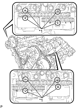
Text in Illustration *1 Timing Mark Check that the timing marks of the camshaft timing gears are aligned with the timing marks of the bearing cap as shown in the illustration.
If not, turn the crankshaft 1 revolution (360°) and align the timing marks as described above.
-
-
REMOVE NO. 1 CHAIN TENSIONER ASSEMBLY
-
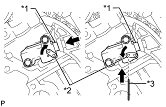
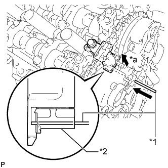
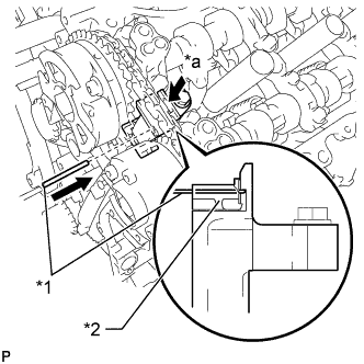
Text in Illustration *1 Plunger *2 Stopper Plate *3 Pin Move the stopper plate upward to release the lock, and push the plunger deep into the tensioner.
-
Move the stopper plate downward to set the lock, and insert a pin of 1.27 mm (0.0500 in.) diameter into the stopper plate's hole.
-
Remove the 2 bolts and chain tensioner.
-
-
REMOVE CHAIN TENSIONER SLIPPER
-
Remove the chain tensioner slipper.
-
-
REMOVE CHAIN SUB-ASSEMBLY
-
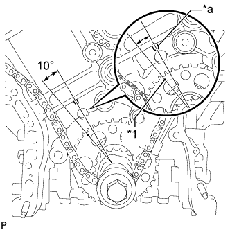
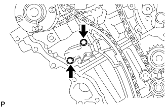
Text in Illustration *1 Timing Mark *a Center Line Turn the crankshaft counterclockwise 10° to loosen the chain of the crankshaft timing sprocket.
-
Remove the pulley set bolt.
-
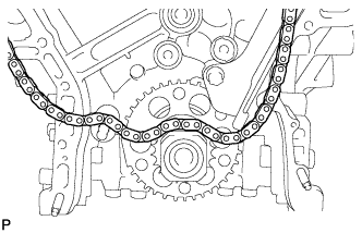
Remove the chain from the crankshaft timing sprocket and place it on the crankshaft.
-
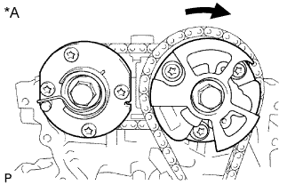
Text in Illustration *A for Bank 1 Turn the camshaft timing gear assembly on bank 1 clockwise (approximately 60°) and set it as shown in the illustration. Be sure to loosen the chain between the banks.
-
Remove the chain.
-
-
REMOVE CAMSHAFT TIMING GEARS AND NO. 2 CHAIN (for Bank 1)
-
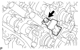
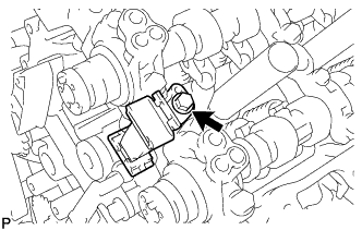
Text in Illustration *1 Pin *2 Plunger *a Push While raising the No. 2 chain tensioner, insert a pin of 1.0 mm (0.0394 in.) diameter into the hole to hold the No. 2 chain tensioner.
-
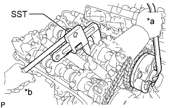
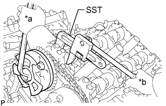
Text in Illustration *a Turn *b Hold Using SST to hold the hexagonal portion of each camshaft, loosen the flange bolts of the camshaft timing gear assembly and the camshaft timing exhaust gear assembly RH.
- SST
- 09922-10010
Note
-
Be careful not to damage the cylinder head with SST.
-
Do not loosen the other bolts. If any of the bolts is loosened, replace the camshaft timing gear assembly and/or the camshaft timing exhaust gear assembly with a new one.
-
Remove the 2 bolts and the camshaft timing gear assembly together with the No. 2 chain.
-
-
REMOVE NO. 2 CHAIN TENSIONER ASSEMBLY
-
Remove the bolt and No. 2 chain tensioner.
-
-
REMOVE CAMSHAFT BEARING CAP (for Bank 1)
-
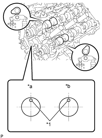
Text in Illustration *1 Knock Pin *a IN *b EX Check that the camshafts are positioned as shown in the illustration.
-
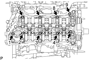
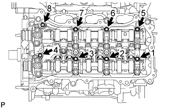
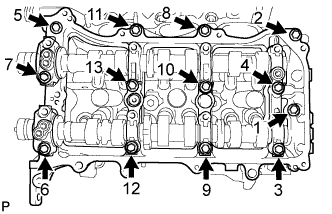
Uniformly loosen and remove the 9 bearing cap bolts in several steps and in the sequence shown in the illustration.
-
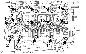
Uniformly loosen and remove the 15 bearing cap bolts in several steps and in the sequence shown in the illustration.
Note
Uniformly loosen the bolts while keeping the camshaft level.
-
-
REMOVE FUEL PUMP LIFTER HOUSING
-
Remove the fuel pump lifter housing.
-
-
REMOVE CAMSHAFT
-
REMOVE NO. 2 CAMSHAFT
-
REMOVE CAMSHAFT HOUSING SUB-ASSEMBLY RH
-
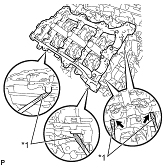
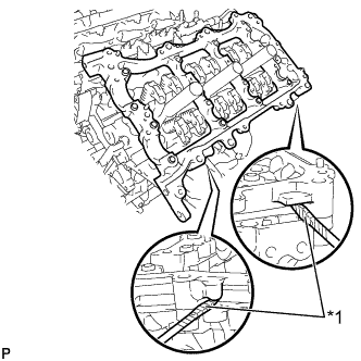
Text in Illustration *1 Protective Tape Remove the camshaft housing RH by prying between the cylinder head and camshaft housing RH with a screwdriver.
Note
Be careful not to damage the contact surfaces of the cylinder head and camshaft housing RH.
Tech Tips
Tape the screwdriver tip before use.
-
-
REMOVE CAMSHAFT TIMING GEARS AND NO. 2 CHAIN (for Bank 2)
-
Text in Illustration *1 Pin *2 Plunger *a Push While pushing down the No. 3 chain tensioner, insert a pin of 1.0 mm (0.0394 in.) diameter into the hole to hold the No. 3 chain tensioner.
-
Text in Illustration *a Turn *b Hold Using SST to hold the hexagonal portion of each camshaft, loosen the flange bolts of the camshaft timing gear assembly and the camshaft timing exhaust gear assembly LH.
- SST
- 09922-10010
Note
-
Be careful not to damage the cylinder head with SST.
-
Do not loosen the other bolts. If any of the bolts is loosened, replace the camshaft timing gear assembly and/or the camshaft timing exhaust gear assembly with a new one.
-
Remove the 2 bolts and the camshaft timing gear together with the No. 2 chain.
-
-
REMOVE NO. 3 CHAIN TENSIONER ASSEMBLY
-
Remove the bolt and No. 3 chain tensioner.
-
-
REMOVE CAMSHAFT BEARING CAP (for Bank 2)
-
Text in Illustration *1 Knock Pin *a IN *b EX Check that the camshafts are positioned as shown in the illustration.
-
Uniformly loosen and remove the 8 bearing cap bolts in several steps and in the sequence shown in the illustration.
-
Uniformly loosen and remove the 13 bearing cap bolts in several steps and in the sequence shown in the illustration.
Note
Uniformly loosen the bolts while keeping the camshaft level.
-
Remove the 5 camshaft bearing caps.
-
-
REMOVE NO. 3 CAMSHAFT SUB-ASSEMBLY
-
REMOVE NO. 4 CAMSHAFT SUB-ASSEMBLY
-
REMOVE CAMSHAFT HOUSING SUB-ASSEMBLY LH
-
Text in Illustration *1 Protective Tape Remove the camshaft housing LH by prying between the cylinder head LH and camshaft housing LH with a screwdriver.
Note
Be careful not to damage the contact surfaces of the cylinder head and camshaft housing LH.
Tech Tips
Tape the screwdriver tip before use.
-
-
REMOVE NO. 1 CHAIN VIBRATION DAMPER
-
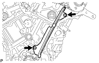
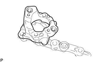
Remove the 2 bolts and No. 1 chain vibration damper.
-
-
REMOVE NO. 2 CHAIN VIBRATION DAMPER
-
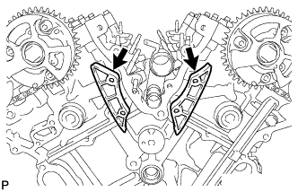
Remove the 2 No. 2 chain vibration dampers.
-
-
REMOVE NO. 1 VALVE ROCKER ARM SUB-ASSEMBLY
-
Remove the 24 No. 1 valve rocker arms.
Tech Tips
Arrange the removed parts in the correct order.
-
-
REMOVE VALVE LASH ADJUSTER ASSEMBLY
-
Remove the 24 valve lash adjusters from the cylinder head.
Tech Tips
Arrange the removed parts in the correct order.
-
-
REMOVE VALVE STEM CAP
-
Remove the 24 valve stem caps.
Tech Tips
Arrange the removed parts in the correct order.
-
-
REMOVE REAR WATER BY-PASS JOINT
-
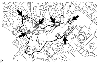
Remove the 2 bolts, 4 nuts and water by-pass joint.
-
Remove the 2 gaskets and O-ring.
-
-
REMOVE NO. 2 FUEL PIPE SUB-ASSEMBLY
-
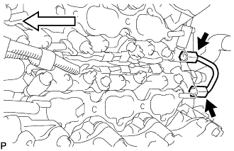
Loosen the 2 union nuts and remove the No. 2 fuel pipe sub-assembly from the fuel delivery pipe.
Text in Illustration 
Front
-
-
REMOVE FUEL DELIVERY PIPE LH
-

Remove the bolt and detach the 2 wire harness clamps.
Text in Illustration Front -
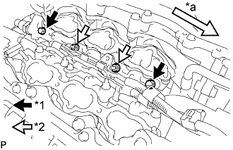
Text in Illustration *1 Bolt *2 Nut *a Front Remove the 2 bolts and 2 nuts.
-
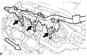
With the connectors still connected, disconnect the fuel delivery pipe LH.
Text in Illustration Front Note
-
Make sure that the fuel delivery pipe is disconnected from the delivery pipe (LH side).
-
Be extremely careful not to touch or strike the tips of the injectors.
-
Pull and remove the fuel pipe in a straight line without tilting it.
-
-
Disconnect the 3 injector connectors.
-
-
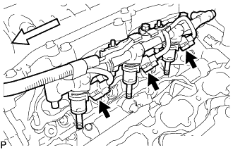
REMOVE FUEL DELIVERY PIPE RH
-
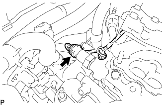
Disconnect the fuel pressure sensor connector.
Note
Do not pull the wire harness of the fuel pressure sensor excessively.
-
Remove the bolt and detach the wire harness clamp.
Text in Illustration Front -
Text in Illustration *1 Bolt *2 Nut *a Front Remove the 2 bolts and 2 nuts.
-
With the connectors still connected, disconnect the fuel delivery pipe RH.
Text in Illustration Front Note
-
Be extremely careful not to touch or strike the tips of the injectors.
-
Pull and remove the fuel pipe in a straight line without tilting it.
-
-
Disconnect the 3 injector connectors.
-
-
REMOVE FUEL INJECTOR ASSEMBLY
-
Fix the fuel delivery pipe in a vise between aluminum plates.
Note
-
Do not tighten the vise more than necessary.
-
Do not damage the fuel injector assemblies.
-
-
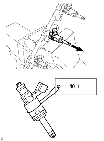
Remove the fuel injector assemblies from the fuel delivery pipe LH and fuel delivery pipe RH.
Note
-
When removing an injector, pull the injector straight out to avoid damaging the O-ring seal surfaces of the fuel delivery pipe LH and fuel delivery pipe RH.
-
After removing the injector, check that the O-ring, No. 1 fuel injector back-up ring and No. 3 fuel injector back-up ring are not remaining on the fuel delivery pipe. If any of the parts remain on the fuel delivery pipe, remove them.
-
Attach a label to the removed injector assembly to distinguish it from other cylinders.
-
-
Remove the nozzle holder clamps from the injectors.
-
Using needle-nose pliers, remove the No. 3 fuel injector back-up ring from the injector assembly.
Note
Do not damage the part contacting the O-ring.
-
Remove the O-ring and No. 1 fuel injector back-up ring.
-
Remove the C-rings and injector vibration insulators from the injectors.
-
-
REMOVE FUEL INJECTOR SEAL
-
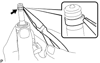
Using the tips of a pair of needle nose pliers, pinch and pull one of the injector seals at several points to stretch it. Repeat this for the other injector seal.
Note
-
Excessively pinching the injector seal may damage the groove of the injector.
-
If an injector is dropped or the tips of the injectors are struck, replace it with a new one.
-
-
Remove the injector seal from the injector.
-
-
REMOVE CYLINDER HEAD SUB-ASSEMBLY
-
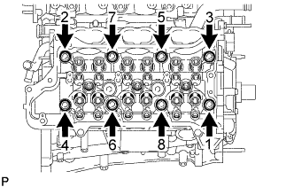
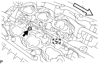
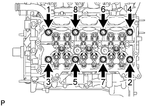
Using a 10 mm bi-hexagon wrench, uniformly loosen the 8 bolts in the sequence shown in the illustration. Remove the 8 cylinder head bolts and plate washers.
Note
-
Be careful not to drop washers into the cylinder head.
-
Cylinder head warpage or cracking could result from removing bolts in an incorrect order.
Tech Tips
Be sure to keep separate the removed parts for each installation position.
-
-
Remove the cylinder head.
-
-
REMOVE CYLINDER HEAD GASKET
-
REMOVE CYLINDER HEAD LH
-
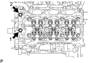
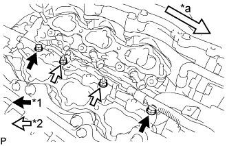
Uniformly loosen and remove the bolts in the sequence shown in the illustration.
-
Using a 10 mm bi-hexagon wrench, uniformly loosen the 8 bolts in the sequence shown in the illustration. Remove the 8 cylinder head bolts and plate washers.
Note
-
Be careful not to drop washers into the cylinder head.
-
Cylinder head warpage or cracking could result from removing bolts in an incorrect order.
Tech Tips
Be sure to keep separate the removed parts for each installation position.
-
-
Remove the cylinder head LH.
-
-
REMOVE NO. 2 CYLINDER HEAD GASKET
-
INSPECT CYLINDER HEAD SET BOLT
-
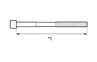
Using a vernier caliper, measure the length of the cylinder head set bolt from the seat to the end.
Standard length 141.3 to 142.7 mm (5.56 to 5.62 in.) Maximum length 143.7 mm (5.66 in.) Text in Illustration *1 Measurement Length If the length is more than the maximum, replace the cylinder head set bolt.
-
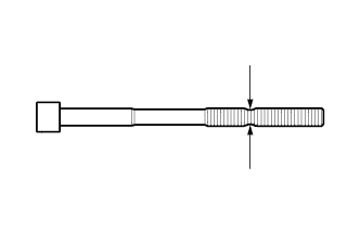
Using a vernier caliper, measure the diameter of the elongated thread at the narrowest visible area.
Standard diameter 10.80 to 11.00 mm (0.425 to 0.433 in.) Minimum diameter 10.70 mm (0.421 in.) If the diameter is less than the minimum, replace the cylinder head set bolt.
Tech Tips
If a visual check reveals no excessively thin areas, check the center of the bolt (refer to illustration) and find the area that has the smallest diameter.
-