CAMSHAFT REMOVAL

-
REMOVE INVERTER WITH CONVERTER ASSEMBLY
-
REMOVE ECM
-
REMOVE FUEL PUMP ASSEMBLY
-
REMOVE NO. 1 ENGINE COVER
-
Remove the 3 clips and No. 1 engine cover.
-
-
REMOVE INJECTOR DRIVER
-
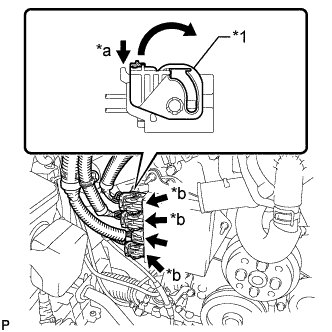
Text in Illustration *1 Lock Lever *a Release *b Lock with Connector Move the lock levers in the direction indicated by the arrow to release the 3 connector locks. Disconnect the 4 connectors from the injector driver.
-
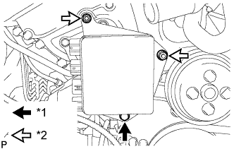
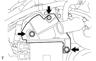
Text in Illustration *1 Bolt *2 Nut Remove the bolt, 2 nuts and injector driver.
Note
Be careful not to drop or strike the injector driver.
-
-
REMOVE ENGINE COVER
-
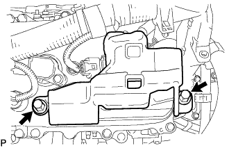
Remove the 2 clips and engine cover.
-
-
REMOVE PCV VALVE SUB-ASSEMBLY
-
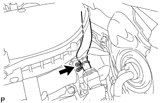
Disconnect the PCV valve hose.
-
Using a 22 mm socket wrench, remove the PCV valve from the No. 2 separator case.
-
-
DISCONNECT NO. 2 WATER BY-PASS PIPE SUB-ASSEMBLY
-
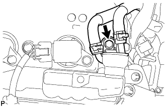
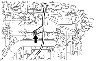
Remove the bolt and disconnect the No. 2 water by-pass pipe.
-
-
REMOVE IGNITION COIL ASSEMBLY
-
for RHD:
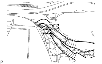
Detach the 2 wire harness clamps from the inverter bracket.
-
for RHD:
Remove the 2 bolts and inverter bracket from the inverter.
-
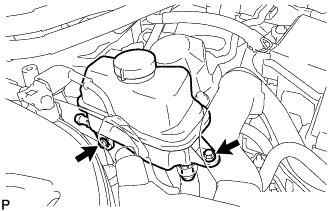
Remove the 2 bolts and disconnect the inverter reservoir tank assembly.
-
for Bank 1:
-
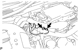
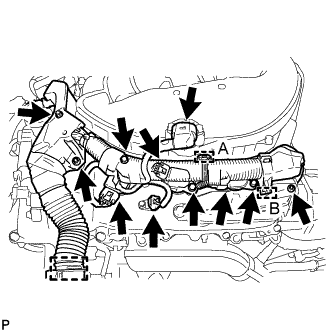
Remove the 3 nuts and disconnect the clamp labeled A using a clip remover. Then, disconnect the clamp labeled B using needle-nose pliers.
Note
Do not damage the claws of the clamp.
-
Disconnect the manifold absolute pressure sensor connector, VVT sensor connector and 3 ignition coil connectors to disconnect the engine wire.
-
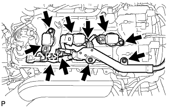
Remove the 3 bolts and 3 ignition coils.
-
-
for Bank 2:
-
Remove the 2 nuts and disconnect the clamp.
-
Disconnect the VVT sensor connector and 3 ignition coil connectors to disconnect the engine wire.
-
Remove the 3 bolts and 3 ignition coils.
-
-
-
REMOVE SPARK PLUG
-
Remove the 6 spark plugs.
-
-
REMOVE NO. 2 OIL LEVEL DIPSTICK GUIDE
-
Remove the oil level dipstick.
-
Remove the bolt and No. 2 oil level dipstick guide.
-
Remove the O-ring from the No. 2 oil level dipstick guide.
-
-
REMOVE CYLINDER HEAD COVER SUB-ASSEMBLY LH
-
Detach the clamps and disconnect the connectors to disconnect the wire harness from the cylinder head cover LH.
-
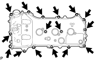
Remove the 16 bolts, cylinder head cover LH and gasket.
-
Remove the 5 gaskets.
-
-
REMOVE CYLINDER HEAD COVER SUB-ASSEMBLY
-
Detach the clamps and disconnect the connectors to disconnect the wire harness from the cylinder head cover.
-
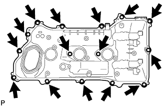
Remove the 15 bolts, cylinder head cover and gasket.
-
Remove the 5 gaskets.
-
-
REMOVE SPARK PLUG TUBE GASKET
-
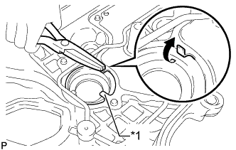
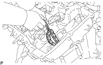
Text in Illustration *1 Claw Pry up the claws of the ventilation baffle plate.
Note
Do not deform the claws of the baffle plate more than necessary.
-
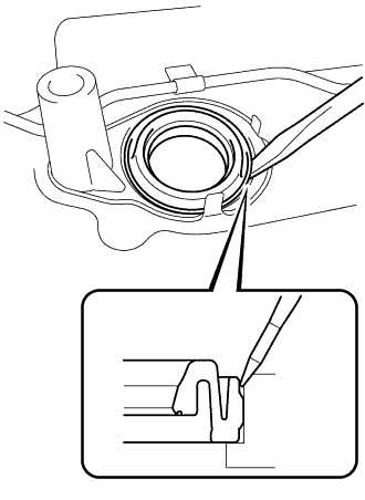
Using a screwdriver as shown in the illustration, deform each spark plug tube gasket inwards and remove the 6 spark plug tube gaskets from the the cylinder head cover.
Note
-
As much as possible prevent the plug tube gaskets from being deformed. The removed gaskets will be used when reinstalling the gaskets.
-
Do not damage the connection of the cylinder head cover.
-
Make sure not to damage the spark plug tube gasket and cylinder head cover when inserting the screwdriver in the joint area.
Tech Tips
If the cylinder head cover is damaged, smooth the surface with 400-grit sandpaper.
-
-
-
REMOVE TIMING CHAIN COVER PLATE
-
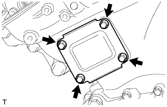
Remove the 4 bolts, timing chain cover plate and gasket.
-
-
SET NO. 1 CYLINDER TO TDC/COMPRESSION
-
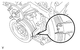
Turn the crankshaft pulley and align the notch with the "0" timing mark of the timing chain cover.
-
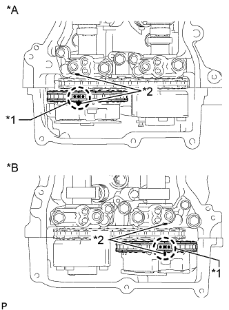
Text in Illustration *A for Bank 2 *B for Bank 1 *1 Paint Mark *2 Timing Mark Check that the timing marks of the camshaft timing gears are aligned with the timing marks of the bearing caps as shown in the illustration.
Tech Tips
If the marks are not aligned, turn the crankshaft again to align the marks.
-
Place paint marks on the chain in alignment with the timing marks on each camshaft timing gear and bearing cap.
Tech Tips
Be sure to place the paint marks on 2 links of the chain and on the sprockets of the camshaft timing gears at the locations of the timing marks of the camshaft timing gears.
-
-
REMOVE NO. 1 CHAIN TENSIONER ASSEMBLY
-
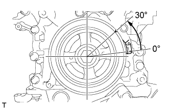
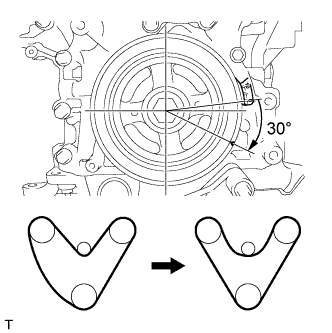
Turn the crankshaft approximately 30° counterclockwise so that there is some slack in the chain.
Tech Tips
This prevents the valves and pistons from interfering with each other.
-
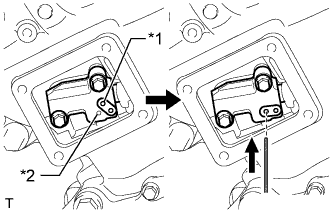
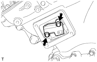
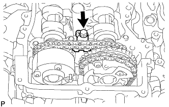
Text in Illustration *1 Lever Hole *2 Tensioner Hole Align the hole in the lever of the tensioner with the hole in the tensioner body as shown in the illustration, and then insert a pin with a diameter of 1.27 mm (0.0500 in.) into the hole.
-
Turn the crankshaft clockwise and align the notch with the "0" timing mark of the timing chain cover.
-
Remove the 2 bolts and No. 1 chain tensioner.
Note
Do not drop the No. 1 chain tensioner or bolts into the timing chain cover.
-
-
SEPARATE CHAIN SUB-ASSEMBLY
-
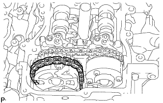
Turn the crankshaft clockwise until it is in the position shown in the illustration so that there is some slack in the chain between the banks.
CAUTION:
As the camshafts turn suddenly, do not touch the camshafts or camshaft timing gears.
Tech Tips
When turning the crankshaft, engine oil may spray out of the oil holes.
-
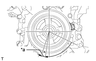
Text in Illustration *a 5 to 10° Turn the crankshaft clockwise until it is in the position shown in the illustration so that the chain can be removed easily.
Tech Tips
When turning the crankshaft, engine oil may spray out of the oil holes.
-
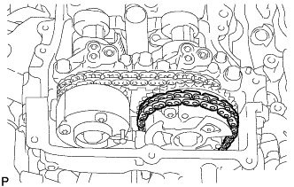
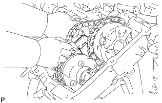
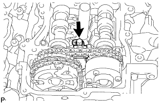
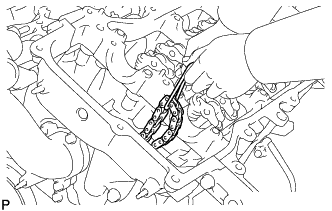
Remove the chain from the sprocket of the camshaft timing gear and set it on the camshaft timing gear.
CAUTION:
As the camshaft may turn suddenly and pinch your fingers when the chain is removed, pinch the chain and lift it upward to remove it from the sprocket.
-
-
REMOVE CAMSHAFT BEARING CAP (for Bank 1)
-
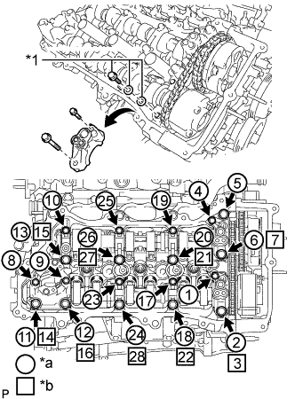
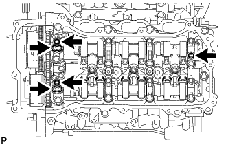
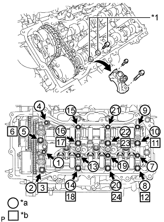
Text in Illustration *1 Service Bolt and Washers (used to temporarily secure the camshaft housing) *a Part to be removed *b Install the service bolts and washers to temporarily secure the camshaft housing Remove the bolts and bearing caps in the order shown in the illustration. Immediately after removing the bearing caps, install the service bolts and washers in the order shown in the illustration.
- Torque:
- 10 N*m { 102 kgf*cm, 7 ft.*lbf }
Note
-
Do not install the bearing caps when installing the service bolts and washers.
-
Be sure to follow the numerical order when performing this procedure.
-
Do not allow the service bolts and washers to contact the camshaft.
-
Do not drop the service bolts and washers into the cylinder head.
Tech Tips
-
Arrange the removed parts so that they can be reinstalled in their original locations.
-
Part number for the service bolts used to temporarily secure the camshaft housing: 91551-F0850 (9 bolts)
-
Part number for the service washers used to temporarily secure the camshaft housing: 90201-12028 (18 washers)
-
-
REMOVE NO. 2 CAMSHAFT
-
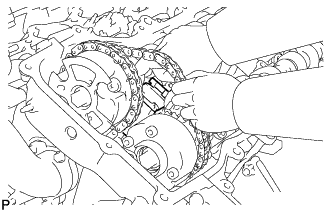
Remove the bolt of the No. 2 chain tensioner.
-
Remove the No. 2 chain tensioner while lifting up the No. 2 camshaft.
-
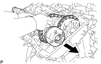
While lifting up the No. 2 camshaft, pass it through the No. 2 chain and pull it out towards the front of the vehicle to remove it.
-
-
REMOVE CAMSHAFT
-
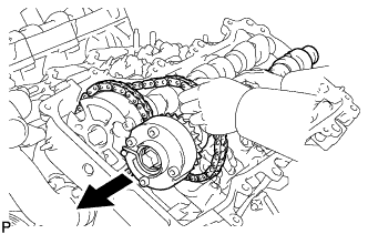
Lift up the rear of the camshaft so that it is at an angle.
-
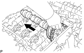
Remove the chain from the camshaft timing gear and pull out the camshaft and No. 2 chain towards the rear of the vehicle to remove them.
Note
Do not drop the chain into the gap between the engine and cover.
-
Suspend the chain with a string or equivalent.
-
-
SEPARATE CHAIN SUB-ASSEMBLY
-
Turn the crankshaft counterclockwise and align the notch with the "0" timing mark of the timing chain cover.
-
Remove the chain from the sprocket of the camshaft timing gear and set it on the camshaft timing gear.
CAUTION:
As the camshaft may turn suddenly and pinch your fingers when the chain is removed, pinch the chain and lift it upward to remove it from the sprocket.
-
-
REMOVE CAMSHAFT BEARING CAP (for Bank 2)
-
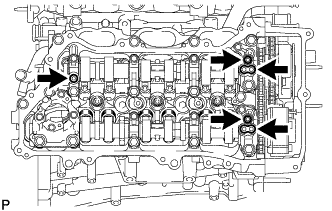
Text in Illustration *1 Service Bolt and Washers (used to temporarily secure the camshaft housing) *a Part to be removed *b Install the service bolts and washers to temporarily secure the camshaft housing Remove the bolts and bearing caps in the order shown in the illustration. Immediately after removing the bearing caps, install the service bolts and washers in the order shown in the illustration.
- Torque:
- 10 N*m { 102 kgf*cm, 7 ft.*lbf }
Note
-
Do not install the bearing caps when installing the service bolts and washers.
-
Be sure to follow the numerical order when performing this procedure.
-
Do not allow the service bolts and washers to contact the camshaft.
-
Do not drop the service bolts and washers into the cylinder head.
Tech Tips
-
Arrange the removed parts so that they can be reinstalled in their original locations.
-
Part number for the service bolts used to temporarily secure the camshaft housing: 91551-F0850 (8 bolts)
-
Part number for the service washers used to temporarily secure the camshaft housing: 90201-12028 (16 washers)
-
-
REMOVE NO. 4 CAMSHAFT SUB-ASSEMBLY
-
Remove the bolt of the No. 3 chain tensioner.
-
Remove the No. 3 chain tensioner while lifting up the No. 4 camshaft.
-
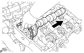
While lifting up the No. 4 camshaft, pass it through the No. 2 chain and pull it out towards the front of the vehicle to remove it.
-
-
REMOVE NO. 3 CAMSHAFT SUB-ASSEMBLY
-
Lift up the rear of the camshaft so that it is at an angle.
-
Remove the chain from the camshaft timing gear and pull out the No. 3 camshaft and No. 2 chain towards the rear of the vehicle to remove them.
Note
Do not drop the chain into the gap between the engine and cover.
-
Suspend the chain with a string or equivalent.
-
-
INSPECT CAMSHAFT TIMING GEAR ASSEMBLY
-
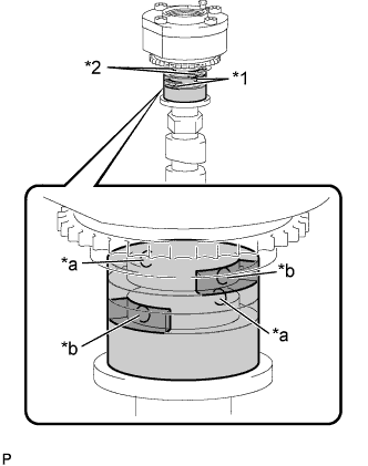
Check the lock of the camshaft timing gear assembly.
-
Clamp the camshaft in a vise, and confirm that the camshaft timing gear assembly is locked.
Note
Be careful not to damage the camshaft.
-
-
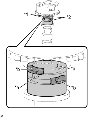
Text in Illustration *1 Advanced Side Path *2 Retard Side Path *a Open *b Close 
Rubber 
Vinyl Tape Release the lock pin.
-
Cover the 4 oil paths of the cam journal with vinyl tape as shown in the illustration.
Tech Tips
The 2 advance side paths are located in the camshaft groove. Plug one of the paths with a rubber piece.
-
Break through the tape on the advance side path and the retard side path on the opposite side of the hole of the advance side path as shown in the illustration.
-
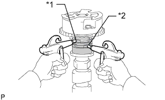
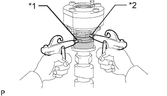
Text in Illustration *1 Advanced Side Path *2 Retard Side Path Apply approximately 200 kPa (2.0 kgf/cm2, 28 psi) of air pressure to the 2 opened paths.
CAUTION:
Cover the paths with a piece of cloth when applying pressure to prevent oil from spraying.
-
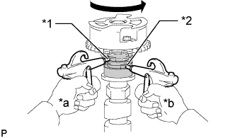
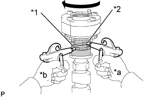
Text in Illustration *1 Advance Side Path *2 Retard Side Path *a Hold Pressure *b Decompress Check that the camshaft timing gear assembly rotates in the advance direction when reducing the air pressure applied to the retard side path.
Tech Tips
This operation releases the lock pin at the most retarded position.
-
When the camshaft timing gear assembly reaches the most advanced position, release the air pressure first from the retard side path and next from the advance side path.
Note
Do not release the air pressure from the advance side path first. The gear may abruptly shift in the retard direction and break the lock pin.
-
-
Check for smooth rotation.
-
Turn the camshaft timing gear assembly within its movable range (21°) 2 or 3 times, but do not turn it to the most retarded position. Make sure that the gear turns smoothly.
Note
Do not use air pressure to perform the smooth operation check.
-
-
Check the lock in the most retarded position.
-
Confirm that the camshaft timing gear assembly locks at the most retarded position.
-
-
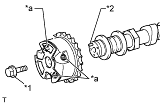
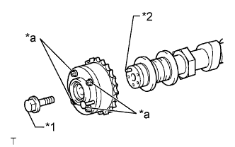
Text in Illustration *1 Flange Bolt *2 Straight Pin *a Do Not Remove Remove the flange bolt and camshaft timing gear assembly.
Note
-
Do not remove the other 3 bolts.
-
If planning to reuse the camshaft timing gear, be sure to release the straight pin lock before installing the camshaft timing gear.
-
-
-
INSPECT CAMSHAFT TIMING EXHAUST GEAR ASSEMBLY
-
Check the camshaft timing exhaust gear lock.
-
Make sure that the camshaft timing exhaust gear assembly locks.
-
-
Text in Illustration *1 Advanced Side Path *2 Retard Side Path *a Open *b Close Rubber Vinyl Tape Release the lock pin.
-
Cover the 4 oil paths of the cam journal with vinyl tape as shown in the illustration.
Tech Tips
The 2 advance side paths are located in the camshaft groove. Plug one of the paths with a rubber piece.
-
Break through the tape on the advance side path and the retard side path on the opposite side of the hole of the advance side path as shown in the illustration.
-
Text in Illustration *1 Advanced Side Path *2 Retard Side Path Apply approximately 200 kPa (2.0 kgf/cm2, 28 psi) of air pressure to the 2 opened paths (the advance side path and the retard side path).
CAUTION:
Cover the paths with a piece of cloth when applying pressure to prevent oil from spraying.
-
Text in Illustration *1 Advance Side Path *2 Retard Side Path *a Hold Pressure *b Decompress Make sure that the camshaft timing exhaust gear assembly rotates in the retard direction when reducing the air pressure applied to the advance side path.
Tech Tips
The lock pin is released and the camshaft timing exhaust gear assembly turns in the retard direction.
-
When the camshaft timing exhaust gear assembly moves to the most retarded position, release the air pressure first from the advance side path, and then release the air pressure from the retard side path.
Note
Be sure to release the air pressure from the advance side path first. If the air pressure of the retard side path is released first, the camshaft timing exhaust gear assembly may abruptly shift in the advance direction and break the lock pin or other parts.
-
-
Check for smooth rotation.
-
Turn the camshaft timing exhaust gear assembly within its movable range (18.5°) 2 or 3 times, but do not turn it to the most advanced position. Make sure that the gear assembly turns smoothly.
Note
When the air pressure is released from the advance side path and then from the retard side path, the gear assembly automatically returns to the most advanced position due to the advance assist spring operation and locks. Gradually release the air pressure from the retard side path before performing the smooth rotation check.
-
-
Check the lock at the most advanced position.
-
Make sure that the camshaft timing exhaust gear assembly locks at the most advanced position.
-
-
Text in Illustration *1 Flange Bolt *2 Straight Pin *a Do Not Remove Remove the flange bolt and camshaft timing exhaust gear assembly.
Note
-
Be sure not to remove the other 4 bolts.
-
If planning to reuse the gear, be sure to release the straight pin lock before installing the gear.
-
-