ENGINE UNIT DISASSEMBLY

-
REMOVE OIL FILLER CAP SUB-ASSEMBLY
-
Remove the oil filler cap and gasket.
-
-
REMOVE RADIATOR CAP SUB-ASSEMBLY
-
REMOVE SPARK PLUG
-
Remove the 6 spark plugs.
-
-
REMOVE OIL PAN DRAIN PLUG
-
Remove the drain plug and gasket.
-
-
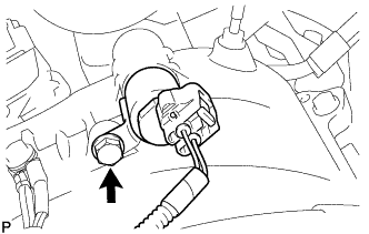
REMOVE PCV VALVE SUB-ASSEMBLY
-
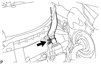
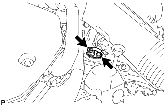
Disconnect the PCV valve hose.
-
Using a 22 mm socket wrench, remove the PCV valve from the No. 2 separator case.
-
-
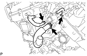
DISCONNECT NO. 2 WATER BY-PASS PIPE SUB-ASSEMBLY
-
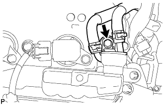
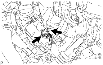
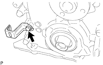
Remove the bolt and disconnect the No. 2 water by-pass pipe.
-
-
REMOVE WATER BY-PASS HOSE ASSEMBLY
-
REMOVE NO. 2 SEPARATOR CASE
-
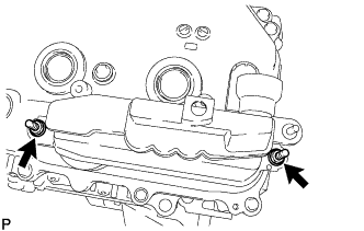
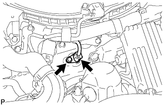
Remove the 2 nuts, No. 2 separator case and O-ring.
-
-
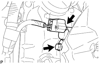
REMOVE VVT SENSOR (for Intake Side of Bank 1)
-
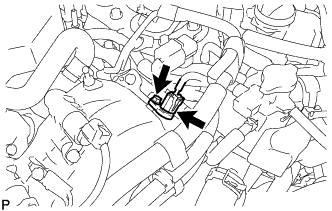
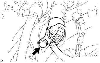
Disconnect the VVT sensor connector.
-
Remove the bolt and VVT sensor.
-
-
REMOVE VVT SENSOR (for Exhaust Side of Bank 1)
-
Disconnect the VVT sensor connector.
-
Remove the bolt and VVT sensor.
-
-
REMOVE VVT SENSOR (for Intake Side of Bank 2)
-
Disconnect the VVT sensor connector.
-
Remove the bolt and VVT sensor.
-
-
REMOVE VVT SENSOR (for Exhaust Side of Bank 2)
-
Disconnect the VVT sensor connector.
-
Remove the bolt and VVT sensor.
-
-
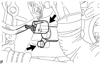
REMOVE CAMSHAFT TIMING OIL CONTROL VALVE ASSEMBLY (for Exhaust Side of Bank 1)
-
Disconnect the oil control valve connector.
-
Remove the bolt and oil control valve.
-
Remove the O-ring from the oil control valve.
-
-
REMOVE CAMSHAFT TIMING OIL CONTROL VALVE ASSEMBLY (for Intake Side of Bank 1)
-
Disconnect the oil control valve connector.
-
Remove the bolt and oil control valve.
-
Remove the O-ring from the oil control valve.
-
-
REMOVE CAMSHAFT TIMING OIL CONTROL VALVE ASSEMBLY (for Intake Side of Bank 2)
-
Disconnect the oil control valve connector.
-
Remove the bolt and oil control valve.
-
Remove the O-ring from the oil control valve.
-
-
REMOVE CAMSHAFT TIMING OIL CONTROL VALVE ASSEMBLY (for Exhaust Side of Bank 2)
-
Disconnect the oil control valve connector.
-
Remove the bolt and oil control valve.
-
Remove the O-ring from the oil control valve.
-
-
REMOVE CRANKSHAFT POSITION SENSOR
-
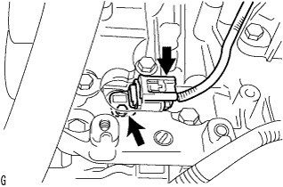
Disconnect the crankshaft position sensor connector.
-
Remove the bolt and crankshaft position sensor.
-
-
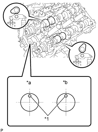
REMOVE CYLINDER BLOCK WATER DRAIN COCK SUB-ASSEMBLY
-
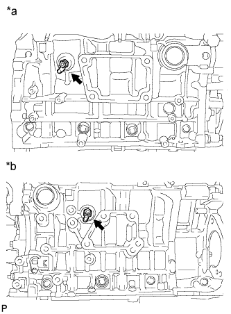
Text in Illustration *a RH Side *b LH Side Remove the water drain cocks from the cylinder block.
-
Remove the water drain cock plugs from the water drain cocks.
-
-
REMOVE OIL FILTER ELEMENT
-
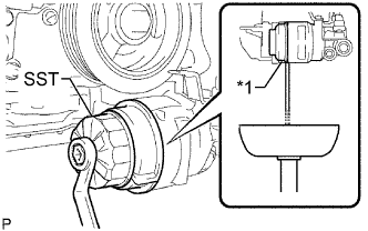
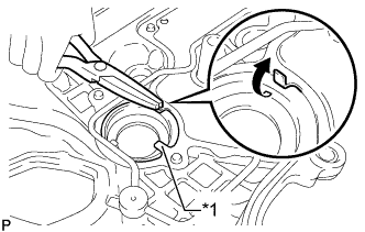
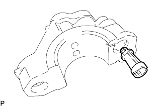
Text in Illustration *1 Rib Using SST, remove the oil filter cap.
- SST
- 09228-06501
Tech Tips
Use a container to catch the draining oil. After the oil filter cap is loosened approximately 4 turns and the cap ribs are vertical, engine oil drains from the gap between the oil filter cap and oil pan.
-
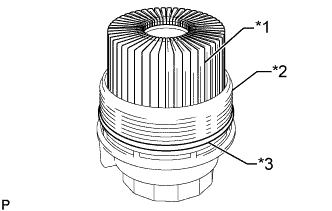
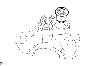
Text in Illustration *1 Oil Filter Element *2 Oil Filter Cap *3 O-ring Remove the oil filter element and O-ring from the oil filter cap.
Note
Do not use any tools to remove the O-ring in order to prevent the cap from being damaged. Be sure to remove it by hand.
-
-
REMOVE CRANKSHAFT PULLEY
-
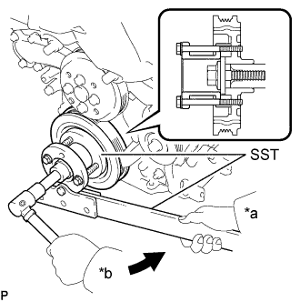
Text in Illustration *a Hold *b Turn Using SST, loosen the pulley bolt.
- SST
- 09213-70011 ( 09213-70020 )
- 09330-00021
-
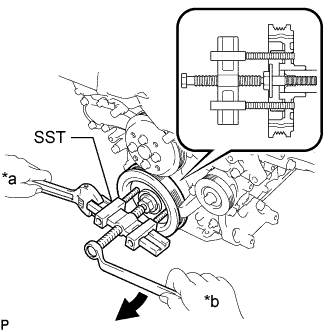
Text in Illustration *a Hold *b Turn Tighten the pulley bolt to 2 or 3 threads of the crankshaft.
-
Using SST, remove the pulley bolt and pulley.
- SST
- 09950-50013 ( 09951-05010, 09952-05010, 09953-05020, 09954-05021 )
Tech Tips
Apply grease to the threads and tip of SST (center bolt) prior to use.
-
-
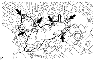
REMOVE WATER INLET SUB-ASSEMBLY
-
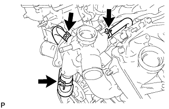
Separate the 3 water by-pass hoses.
-
Remove the 4 bolts, nut and water inlet.
-
Remove the 2 O-rings.
-
Remove the 3 water by-pass hoses.
-
-
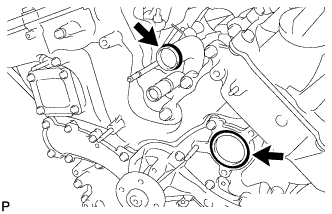
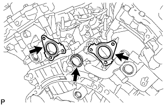
REMOVE WATER INLET WITH THERMOSTAT SUB-ASSEMBLY
-
Remove the 3 nuts and water inlet with thermostat.
-
Remove the gasket from the water inlet.
-
-
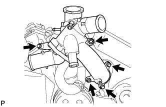
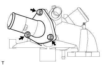
REMOVE REAR WATER BY-PASS JOINT
-
Remove the 2 bolts, 4 nuts and water by-pass joint.
-
Remove the 2 gaskets and O-ring.
-
-
REMOVE FUEL PUMP SPACER GASKET
-
Remove the fuel pump spacer gasket from the cylinder head cover.
-
-
REMOVE CYLINDER HEAD COVER SUB-ASSEMBLY
-
Detach the clamps and disconnect the connectors to disconnect the wire harness from the cylinder head cover.
-
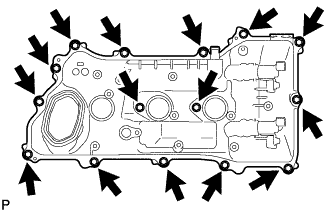
Remove the 15 bolts, cylinder head cover and gasket.
-
Remove the 5 gaskets.
-
-
REMOVE CYLINDER HEAD COVER SUB-ASSEMBLY LH
-
Detach the clamps and disconnect the connectors to disconnect the wire harness from the cylinder head cover LH.
-
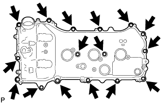
Remove the 16 bolts, cylinder head cover LH and gasket.
-
Remove the 5 gaskets.
-
-
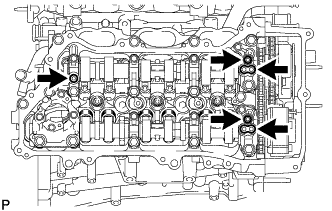
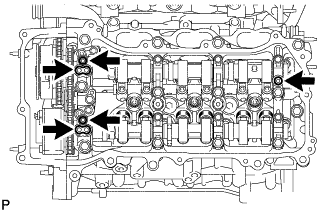
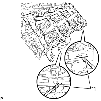
REMOVE SPARK PLUG TUBE GASKET
-
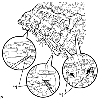
Text in Illustration *1 Claw Pry up the claws of the ventilation baffle plate.
Note
Do not deform the claws of the baffle plate more than necessary.
-
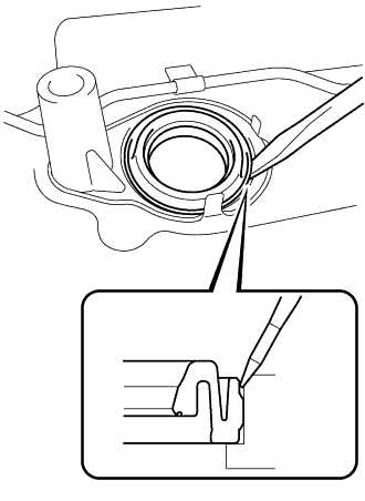
Using a screwdriver as shown in the illustration, deform each spark plug tube gasket inwards and remove the 6 spark plug tube gaskets from the the cylinder head cover.
Note
-
As much as possible prevent the plug tube gaskets from being deformed. The removed gaskets will be used when reinstalling the gaskets.
-
Do not damage the connection of the cylinder head cover.
-
Make sure not to damage the spark plug tube gasket and cylinder head cover when inserting the screwdriver in the joint area.
Tech Tips
If the cylinder head cover is damaged, smooth the surface with 400-grit sandpaper.
-
-
-
REMOVE OIL PAN DRAIN PLUG
-
Remove the oil pan drain plug and gasket.
-
-
REMOVE NO. 2 OIL PAN SUB-ASSEMBLY
-
Remove the 15 bolts and 2 nuts.
Text in Illustration 
Bolt 
Nut -
Insert the blade of an oil pan seal cutter between the oil pans. Cut through the applied sealer and remove the No. 2 oil pan.
Note
Be careful not to damage the contact surfaces of the oil pans.
-
-
REMOVE OIL PAN SUB-ASSEMBLY
-
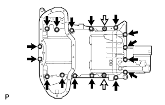
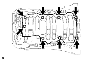
Remove the 16 bolts and 2 nuts.
Text in Illustration Bolt Nut Tech Tips
Be sure to clean the bolts and stud bolts and check the threads for cracks or other damage.
-
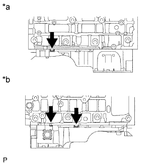
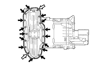
Text in Illustration *a LH Side *b RH Side Remove the oil pan by prying between the oil pan and cylinder block with a screwdriver.
Note
Be careful not to damage the contact surfaces of the cylinder block and oil pan.
Tech Tips
Tape the screwdriver tip before use.
-
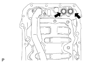
Remove the 2 O-rings.
-
-
REMOVE OIL STRAINER SUB-ASSEMBLY
-
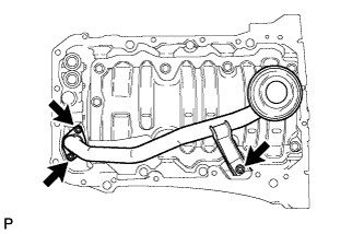
Remove the 3 nuts, oil strainer and gasket.
-
Remove the 8 bolts and baffle plate.
-
-
REMOVE ENGINE REAR OIL SEAL RETAINER
-
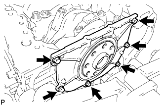
Remove the 6 bolts.
-
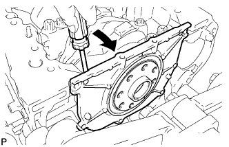
Using a screwdriver, pry out the oil seal retainer.
Text in Illustration Pry Note
Be careful not to damage the engine rear oil seal retainer.
Tech Tips
Tape the screwdriver tip before use.
-
-
REMOVE REAR CRANKSHAFT OIL SEAL
-
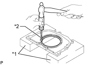
Text in Illustration *1 Wooden Block *2 Protective Tape Place the oil seal retainer on wooden blocks.
Note
Be careful not to damage the engine rear oil seal retainer.
-
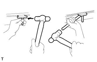
Using a screwdriver and a hammer, tap out the oil seal.
Tech Tips
Tape the screwdriver tip before use.
-
-
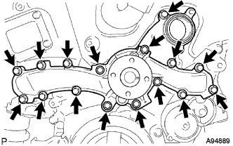
REMOVE TIMING CHAIN COVER SUB-ASSEMBLY
-
Remove the bolt and wire harness clamp bracket.
-
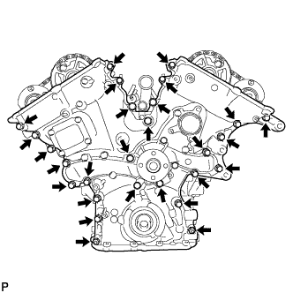
Remove the 25 bolts and 2 nuts shown in the illustration.
-
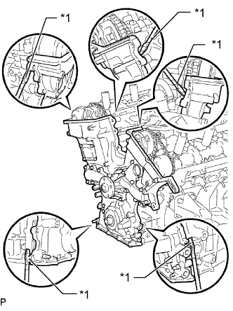
Text in Illustration *1 Protective Tape Remove the timing chain cover by prying between the timing chain cover and cylinder head or cylinder block with a screwdriver.
Note
Be careful not to damage the contact surfaces of the cylinder head, cylinder block and chain cover.
Tech Tips
Tape the screwdriver tip before use.
-
Remove the gasket.
-
-
REMOVE ENGINE WATER PUMP ASSEMBLY
-
Remove the 16 bolts, engine water pump and water pump gasket.
-
-
REMOVE TIMING CHAIN CASE OIL SEAL
-
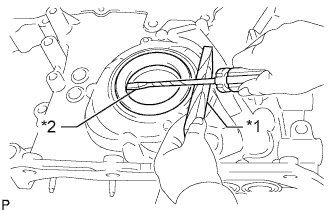
Text in Illustration *1 Wooden Block *2 Protective Tape Using a screwdriver, pry out the oil seal.
Tech Tips
Tape the screwdriver tip before use.
-
-
SET NO. 1 CYLINDER TO TDC/COMPRESSION
-
Temporarily install the pulley set bolt.
-
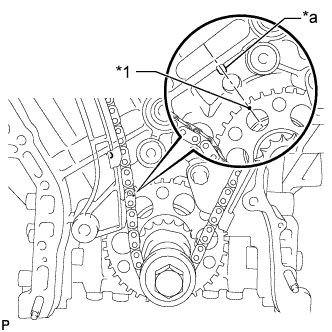
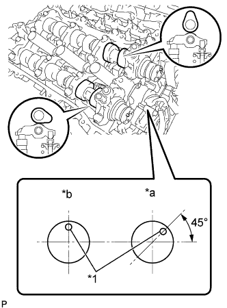
Text in Illustration *1 Timing Mark *a Center Line Set the timing mark on the crank angle sensor plate to the RH block bore center line (TDC/compression).
-
Text in Illustration *1 Timing Mark Check that the timing marks of the camshaft timing gears are aligned with the timing marks of the bearing cap as shown in the illustration.
If not, turn the crankshaft 1 revolution (360°) and align the timing marks as described above.
-
-
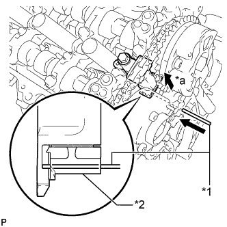
REMOVE NO. 1 CHAIN TENSIONER ASSEMBLY
-
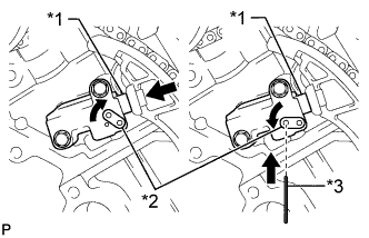
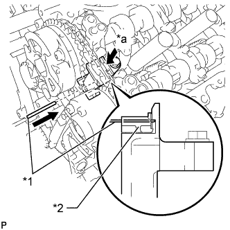
Text in Illustration *1 Plunger *2 Stopper Plate *3 Pin Move the stopper plate upward to release the lock, and push the plunger deep into the tensioner.
-
Move the stopper plate downward to set the lock, and insert a pin of 1.27 mm (0.0500 in.) diameter into the stopper plate's hole.
-
Remove the 2 bolts and chain tensioner.
-
-
REMOVE CHAIN TENSIONER SLIPPER
-
Remove the chain tensioner slipper.
-
-
REMOVE CHAIN SUB-ASSEMBLY
-
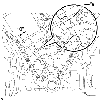
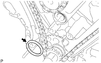
Text in Illustration *1 Timing Mark *a Center Line Turn the crankshaft counterclockwise 10° to loosen the chain of the crankshaft timing sprocket.
-
Remove the pulley set bolt.
-
Remove the chain from the crankshaft timing sprocket and place it on the crankshaft.
-
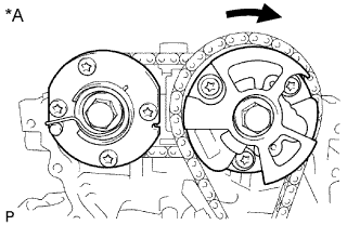
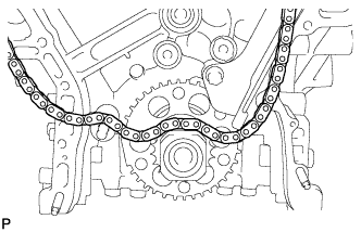
Text in Illustration *A for Bank 1 Turn the camshaft timing gear assembly on bank 1 clockwise (approximately 60°) and set it as shown in the illustration. Be sure to loosen the chain between the banks.
-
Remove the chain.
-
-
REMOVE IDLE SPROCKET ASSEMBLY
-
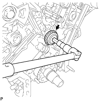
Using a 10 mm hexagon wrench, remove the No. 2 idle gear shaft, idle sprocket and No. 1 idle gear shaft.
-
-
REMOVE NO. 1 CHAIN VIBRATION DAMPER
-
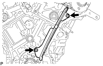
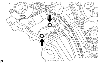
Remove the 2 bolts and No. 1 chain vibration damper.
-
-
REMOVE NO. 2 CHAIN VIBRATION DAMPER
-
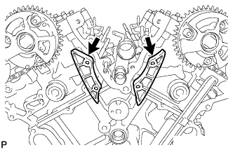
Remove the 2 No. 2 chain vibration dampers.
-
-
REMOVE CRANKSHAFT TIMING SPROCKET
-
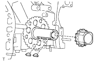
Remove the crankshaft timing sprocket from the crankshaft.
-
Remove the 2 pulley set keys from the crankshaft.
-
-
REMOVE CAMSHAFT TIMING GEARS AND NO. 2 CHAIN (for Bank 1)
-
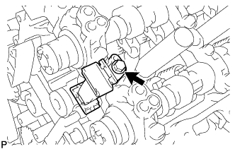
Text in Illustration *1 Pin *2 Plunger *a Push While raising the No. 2 chain tensioner, insert a pin of 1.0 mm (0.0394 in.) diameter into the hole to hold the No. 2 chain tensioner.
-
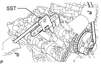
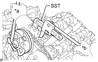
Text in Illustration *a Turn *b Hold Using SST to hold the hexagonal portion of each camshaft, loosen the flange bolts of the camshaft timing gear assembly and the camshaft timing exhaust gear assembly RH.
- SST
- 09922-10010
Note
-
Be careful not to damage the cylinder head with SST.
-
Do not loosen the other bolts. If any of the bolts is loosened, replace the camshaft timing gear assembly and/or the camshaft timing exhaust gear assembly with a new one.
-
Remove the 2 bolts and the camshaft timing gear assembly together with the No. 2 chain.
-
-
REMOVE NO. 2 CHAIN TENSIONER ASSEMBLY
-
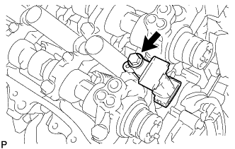
Remove the bolt and No. 2 chain tensioner.
-
-
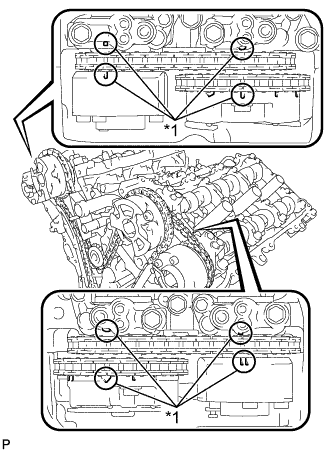
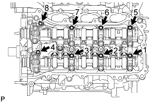
REMOVE CAMSHAFT BEARING CAP (for Bank 1)
-
Text in Illustration *1 Knock Pin *a IN *b EX Check that the camshafts are positioned as shown in the illustration.
-
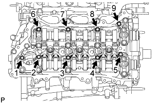
Uniformly loosen and remove the 9 bearing cap bolts in several steps and in the sequence shown in the illustration.
-
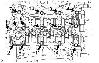
Uniformly loosen and remove the 15 bearing cap bolts in several steps and in the sequence shown in the illustration.
Note
Uniformly loosen the bolts while keeping the camshaft level.
-
-
REMOVE FUEL PUMP LIFTER HOUSING
-
Remove the fuel pump lifter housing.
-
-
REMOVE CAMSHAFT
-
REMOVE NO. 2 CAMSHAFT
-
REMOVE CAMSHAFT HOUSING SUB-ASSEMBLY RH
-
Text in Illustration *1 Protective Tape Remove the camshaft housing RH by prying between the cylinder head and camshaft housing RH with a screwdriver.
Note
Be careful not to damage the contact surfaces of the cylinder head and camshaft housing RH.
Tech Tips
Tape the screwdriver tip before use.
-
-
REMOVE CAMSHAFT TIMING GEARS AND NO. 2 CHAIN (for Bank 2)
-
Text in Illustration *1 Pin *2 Plunger *a Push While pushing down the No. 3 chain tensioner, insert a pin of 1.0 mm (0.0394 in.) diameter into the hole to hold the No. 3 chain tensioner.
-
Text in Illustration *a Turn *b Hold Using SST to hold the hexagonal portion of each camshaft, loosen the flange bolts of the camshaft timing gear assembly and the camshaft timing exhaust gear assembly LH.
- SST
- 09922-10010
Note
-
Be careful not to damage the cylinder head with SST.
-
Do not loosen the other bolts. If any of the bolts is loosened, replace the camshaft timing gear assembly and/or the camshaft timing exhaust gear assembly with a new one.
-
Remove the 2 bolts and the camshaft timing gear together with the No. 2 chain.
-
-
REMOVE NO. 3 CHAIN TENSIONER ASSEMBLY
-
Remove the bolt and No. 3 chain tensioner.
-
-
REMOVE CAMSHAFT BEARING CAP (for Bank 2)
-
Text in Illustration *1 Knock Pin *a IN *b EX Check that the camshafts are positioned as shown in the illustration.
-
Uniformly loosen and remove the 8 bearing cap bolts in several steps and in the sequence shown in the illustration.
-
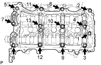
Uniformly loosen and remove the 13 bearing cap bolts in several steps and in the sequence shown in the illustration.
Note
Uniformly loosen the bolts while keeping the camshaft level.
-
Remove the 5 camshaft bearing caps.
-
-
REMOVE NO. 3 CAMSHAFT SUB-ASSEMBLY
-
REMOVE NO. 4 CAMSHAFT SUB-ASSEMBLY
-
REMOVE CAMSHAFT HOUSING SUB-ASSEMBLY LH
-
Text in Illustration *1 Protective Tape Remove the camshaft housing LH by prying between the cylinder head LH and camshaft housing LH with a screwdriver.
Note
Be careful not to damage the contact surfaces of the cylinder head and camshaft housing LH.
Tech Tips
Tape the screwdriver tip before use.
-
-
REMOVE OIL CONTROL VALVE FILTER LH
-
Remove the oil control valve filter LH from the camshaft bearing cap.
-
-
REMOVE OIL CONTROL VALVE FILTER RH
-
Remove the oil control valve filter RH from the camshaft bearing cap.
-
-
REMOVE OIL CHECK VALVE
-
Remove the oil check valve from the camshaft bearing cap.
-
-
REMOVE NO. 1 VALVE ROCKER ARM SUB-ASSEMBLY
-
Remove the 24 No. 1 valve rocker arms.
Tech Tips
Arrange the removed parts in the correct order.
-
-
REMOVE VALVE LASH ADJUSTER ASSEMBLY
-
Remove the 24 valve lash adjusters from the cylinder head.
Tech Tips
Arrange the removed parts in the correct order.
-
-
REMOVE VALVE STEM CAP
-
Remove the 24 valve stem caps.
Tech Tips
Arrange the removed parts in the correct order.
-
-
REMOVE CYLINDER HEAD SUB-ASSEMBLY
-
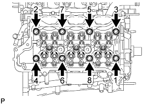
Using a 10 mm bi-hexagon wrench, uniformly loosen the 8 bolts in the sequence shown in the illustration. Remove the 8 cylinder head bolts and plate washers.
Note
-
Be careful not to drop washers into the cylinder head.
-
Cylinder head warpage or cracking could result from removing bolts in an incorrect order.
Tech Tips
Be sure to keep separate the removed parts for each installation position.
-
-
Remove the cylinder head.
-
-
REMOVE CYLINDER HEAD GASKET
-
REMOVE CYLINDER HEAD LH
-
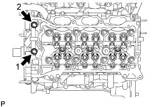
Uniformly loosen and remove the bolts in the sequence shown in the illustration.
-
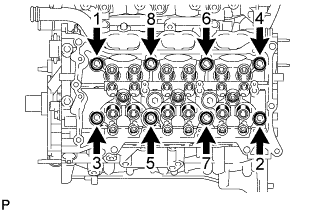
Using a 10 mm bi-hexagon wrench, uniformly loosen the 8 bolts in the sequence shown in the illustration. Remove the 8 cylinder head bolts and plate washers.
Note
-
Be careful not to drop washers into the cylinder head.
-
Cylinder head warpage or cracking could result from removing bolts in an incorrect order.
Tech Tips
Be sure to keep separate the removed parts for each installation position.
-
-
Remove the cylinder head LH.
-
-
REMOVE NO. 2 CYLINDER HEAD GASKET
-
REMOVE NO. 5 ENGINE WIRE
-
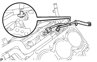
Detach the clamp and remove the No. 5 engine wire.
-
-
REMOVE KNOCK SENSOR
-
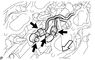
Disconnect the 2 knock sensor connectors.
Text in Illustration Front -
Remove the 2 bolts and 2 knock sensors.
-
-
REMOVE WATER OUTLET PIPE SUB-ASSEMBLY
-
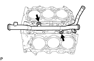
Remove the 2 bolts and water outlet pipe.
-
-
REMOVE NO. 1 STRAIGHT PIN
Note
It is not necessary to remove a No. 1 straight pin unless it is being replaced.
-
REMOVE RING PIN
Note
It is not necessary to remove a ring pin unless it is being replaced.