CYLINDER HEAD GASKET REMOVAL

-
REMOVE EGR COOLER ASSEMBLY (w/ EGR System)
-
REMOVE EXHAUST MANIFOLD CONVERTER SUB-ASSEMBLY
-
INSTALL ENGINE TO ENGINE STAND (w/o EGR System)
-
Install the engine assembly to an engine stand.
Note
-
Adjust the angle of the sling device carefully to prevent the engine assembly or engine hanger from deforming or becoming damaged.
-
Do not perform any procedures while the engine assembly is suspended because doing so may cause the engine assembly to drop, resulting in injury. However, the engine assembly needs to be suspended when it is installed or removed from an engine stand.
-
-
Remove the 2 bolts, No. 1 engine hanger and No. 2 engine hanger.
-
-
REMOVE ENGINE MOTOR CABLE CLAMP BRACKET (w/o EGR System)
-
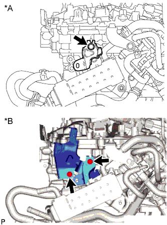
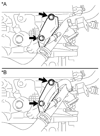
Text in Illustration *A for LHD *B for RHD for LHD:
Remove the bolt and engine motor cable clamp bracket from the EGR cooler assembly.
-
for RHD:
Remove the 2 bolts and engine motor cable clamp bracket from the EGR cooler assembly and cylinder head sub-assembly.
-
-
REMOVE FUEL INJECTOR ASSEMBLY
-
REMOVE FUEL INJECTOR SET
-
REMOVE CAMSHAFT HOUSING SUB-ASSEMBLY
-
REMOVE NO. 6 WATER BY-PASS HOSE (w/o EGR System)
-
Slide the clip and disconnect the No. 6 water by-pass hose from the water by-pass pipe.
-
-
REMOVE NO. 5 WATER BY-PASS HOSE (w/o EGR System)
-
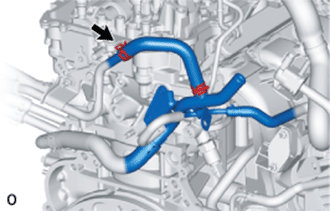
Slide the clip and disconnect the No. 5 water by-pass hose from the water by-pass pipe.
-
-
REMOVE WATER BY-PASS PIPE (w/o EGR System)
-
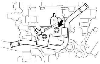
Remove the nut, bolt and water by-pass pipe from the cylinder head sub-assembly.
Text in Illustration 
Bolt 
Nut
-
-
REMOVE NO. 9 WATER BY-PASS HOSE
-
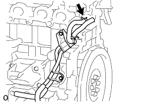
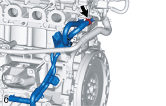
Slide the clip and disconnect the No. 9 water by-pass hose from the cylinder head sub-assembly.
-
-
REMOVE NO. 2 WATER BY-PASS PIPE
-
Text in Illustration *A w/ EGR System *B w/o EGR System Remove the 2 bolts and disconnect the No. 2 water by-pass pipe.
-
-
REMOVE SPARK PLUG
-
Remove the 4 spark plugs from the cylinder head sub-assembly.
Note
If a spark plug has been struck or dropped, replace it.
Tech Tips
Arrange the removed parts in the correct order.
-
-
REMOVE NO. 1 VALVE ROCKER ARM SUB-ASSEMBLY
-
Remove the 16 No. 1 valve rocker arm sub-assemblies from the cylinder head sub-assembly.
Tech Tips
Be sure to keep the removed parts for each installation position separate.
-
-
REMOVE VALVE LASH ADJUSTER ASSEMBLY
-
Remove the 16 valve lash adjuster assemblies from the cylinder head sub-assembly.
Tech Tips
Be sure to keep the removed parts for each installation position separate.
-
-
REMOVE VALVE STEM CAP
-
Remove the 16 valve stem caps from the valve stem ends.
Tech Tips
Be sure to keep the removed parts for each installation position separate.
-
-
REMOVE CYLINDER HEAD SUB-ASSEMBLY
-
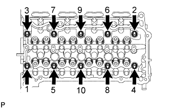
Using a 10 mm bi-hexagon wrench, uniformly loosen the 10 cylinder head set bolts in the sequence shown in the illustration. Remove the 10 cylinder head set bolts and plate washers.
Note
-
Be careful not to drop the plate washers into the cylinder head sub-assembly.
-
Cylinder head sub-assembly warpage or cracking could result from removing cylinder head set bolts in an incorrect order.
Tech Tips
Be sure to keep the removed parts for each installation position separate.
-
-
Remove the cylinder head sub-assembly.
-
-
REMOVE CYLINDER HEAD GASKET
-
Remove the cylinder head gasket from the cylinder block sub-assembly.
-
-
INSPECT CYLINDER HEAD SET BOLT
-
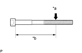
Text in Illustration *a Measurement Point *b Approximately 106 mm (4.17 in.) Using a vernier caliper, measure the diameter of the threads at the measurement point.
Standard diameter 10.85 to 11.00 mm (0.427 to 0.433 in.) Minimum diameter 10.6 mm (0.417 in.) Tech Tips
-
If the diameter is less than the minimum, replace the cylinder head set bolt. Failure to do so may lead to engine damage.
-
If there is any thread deformation, replace the cylinder head set bolt with a new one.
-
-
-
INSPECT CYLINDER HEAD SUB-ASSEMBLY
-
Using a precision straightedge and feeler gauge, measure the warpage of the surfaces which contact the cylinder block sub-assembly and manifolds.
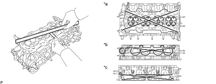
Text in Illustration *a Cylinder Block Sub-assembly Side *b Exhaust Side *c Intake Side - - Maximum Warpage Item Specified Condition Cylinder Block Sub-assembly Side 0.05 mm (0.00197 in.) Intake Side 0.10 mm (0.00394 in.) Exhaust Side 0.10 mm (0.00394 in.) If the warpage is more than the maximum, replace the cylinder head sub-assembly.
-
Using a dye penetrant, check the intake ports, exhaust ports and cylinder surface for cracks. If cracked, replace the cylinder head sub-assembly.
-