CAMSHAFT INSTALLATION

Tech Tips
Perform "Inspection After Repair" after replacing the camshaft, No. 2 camshaft, camshaft timing gear assembly or camshaft timing exhaust gear assembly.
-
w/ EGR System: Click here
-
w/o EGR System: Click here
-
INSTALL VALVE LASH ADJUSTER ASSEMBLY
Note
-
Keep the valve lash adjuster assembly free from dirt and foreign objects.
-
Only use clean engine oil.
-
If the valve lash adjuster assembly is tilted after bleeding, oil will leak. Make sure to bleed the valve lash adjuster assembly again.
-
Bleed the valve lash adjuster assembly Click here.
-
If the plunger moves, bleed the valve lash adjuster assembly again.
-
Place the valve lash adjuster assembly into a container full of new engine oil, and then fill the low pressure chamber with engine oil.
-
Apply engine oil to the outer surface of the valve lash adjuster body and the tip of the plunger, and then install the valve lash adjuster assembly while turning it.
Note
Install the valve lash adjuster assembly to the same place it was removed from.
-
-
INSTALL NO. 1 VALVE ROCKER ARM SUB-ASSEMBLY
-
Apply engine oil to the valve lash adjuster assembly tips and valve stem caps.
-
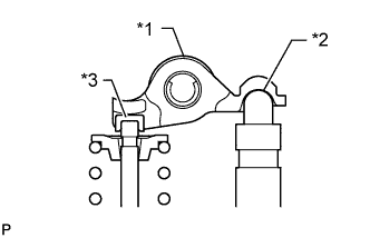
Text in Illustration *1 No. 1 Valve Rocker Arm Sub-assembly *2 Valve Lash Adjuster Assembly *3 Valve Stem Cap Install the 16 No. 1 valve rocker arm sub-assemblies as shown in the illustration.
Note
Install the No. 1 valve rocker arm sub-assembly to the same place it was removed from.
-
-
INSTALL NO. 2 CAMSHAFT BEARING
-
Clean the No. 2 camshaft bearing.
Note
Do not apply engine oil to the No. 2 camshaft bearing or contact surfaces.
-
Install the No. 2 camshaft bearing to the camshaft housing sub-assembly.
-

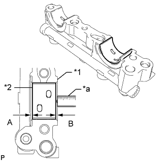
Text in Illustration *1 Camshaft Housing Sub-assembly *2 No. 2 Camshaft Bearing *a Vernier Caliper Using a vernier caliper, measure the distance between the camshaft housing sub-assembly edge and the No. 2 camshaft bearing edge.
Standard distance A = 1.15 to 1.85 mm (0.0453 to 0.0728 in.)
-
-
INSTALL NO. 2 CAMSHAFT
Tech Tips
Perform "Inspection After Repair" after replacing the No. 2 camshaft.
-
w/ EGR System: Click here
-
w/o EGR System: Click here
-
Clean the No. 2 camshaft journals and camshaft housing sub-assembly.
-
Apply a light coat of engine oil to the No. 2 camshaft journals and camshaft housing sub-assembly.
-
Set the No. 2 camshaft to the camshaft housing sub-assembly.
-
-
INSTALL CAMSHAFT
Tech Tips
Perform "Inspection After Repair" after replacing the camshaft.
-
w/ EGR System: Click here
-
w/o EGR System: Click here
-
Clean the camshaft journals and camshaft housing sub-assembly.
-
Apply a light coat of engine oil to the camshaft journals and camshaft housing sub-assembly.
-
Set the camshaft to the camshaft housing sub-assembly.
-
-
INSTALL NO. 1 CAMSHAFT BEARING
-
Clean the No. 1 camshaft bearing.
Note
Do not apply engine oil to the No. 1 camshaft bearing or contact surfaces.
-
Install the No. 1 camshaft bearing to the No. 1 camshaft bearing cap.
-
Text in Illustration *1 No. 1 Camshaft Bearing Cap *2 No. 1 Camshaft Bearing *a Vernier Caliper Using a vernier caliper, measure the distance between the No. 1 camshaft bearing cap edge and the No. 1 camshaft bearing edge.
Standard dimension A - B or B - A = 0 to 0.7 mm (0 to 0.0276 in.)
-
-
INSTALL OIL CONTROL VALVE FILTER
-
Check that there is no foreign matter on the mesh section.
-
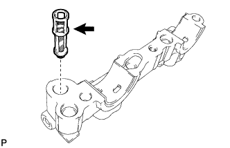
Install the oil control valve filter to the No. 1 camshaft bearing cap.
Note
Do not touch the mesh section on the oil control valve filter.
-
-
INSTALL CAMSHAFT BEARING CAP
-
Clean the camshaft bearing caps.
-
Apply a light coat of engine oil to the camshaft journals and camshaft bearing caps.
-
Install the No. 1 camshaft bearing cap, No. 2 camshaft bearing cap, No. 3 camshaft bearing cap and No. 4 camshaft bearing cap.
-
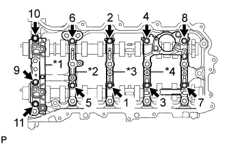
Text in Illustration *1 No. 1 camshaft bearing cap *2 No. 2 camshaft bearing cap *3 No. 3 camshaft bearing cap *4 No. 4 camshaft bearing cap Using several steps, uniformly tighten the 11 bolts in the sequence shown in the illustration.
- Torque:
- 16 N*m { 163 kgf*cm, 12 ft.*lbf }
Note
After installing the No. 1 camshaft bearing cap, No. 2 camshaft bearing cap, No. 3 camshaft bearing cap and No. 4 camshaft bearing cap, make sure that the camshaft and No. 2 camshaft rotate smoothly.
-
-
INSTALL CAMSHAFT HOUSING SUB-ASSEMBLY
-

Text in Illustration *a Seal Packing Apply seal packing in a continuous line as shown in the illustration.
Seal packing Toyota Genuine Seal Packing Black, Three Bond 1207B or equivalent Standard seal diameter 3.0 to 4.0 mm (0.118 to 0.157 in.) Note
-
Remove any oil from the contact surface.
-
Check the bolts and bolt holes and clean them.
-
Install the camshaft housing sub-assembly within 3 minutes and tighten the bolts within 10 minutes after applying seal packing.
-
Do not add engine oil within 2 hours of installation.
-
Do not start the engine for at least 2 hours after the installation.
-
-
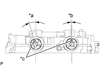
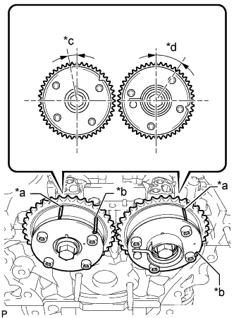
Text in Illustration *a Approximately 17° *b Approximately 2° *c Knock Pin Position the knock pin of the camshaft and No. 2 camshaft as shown in the illustration.
-
Text in Illustration *1 No. 1 Valve Rocker Arm Sub-assembly *2 Valve Lash Adjuster Assembly *3 Valve Stem Cap Make sure that the No. 1 valve rocker arm sub-assemblies are installed as shown in the illustration.
-
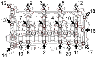
Install the camshaft housing sub-assembly, and then tighten the 20 bolts in the order shown in the illustration.
- Torque:
- 27 N*m { 275 kgf*cm, 20 ft.*lbf }
Standard Bolt Item Length Bolt A 70 mm (2.76 in.) Bolt B 45 mm (1.77 in.) Text in Illustration 
Bolt A 
Bolt B Note
If the bolts have been loosened during the installation, apply seal packing black to the camshaft housing sub-assembly again.
-
-
INSPECT CAMSHAFT TIMING GEAR ASSEMBLY
-
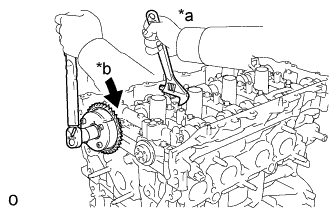
Secure the camshaft between aluminum plates in a vise.
Note
Do not damage the camshaft.
-
Install the camshaft timing gear assembly to the camshaft Click here.
-
Check the lock of the camshaft timing gear assembly.
-
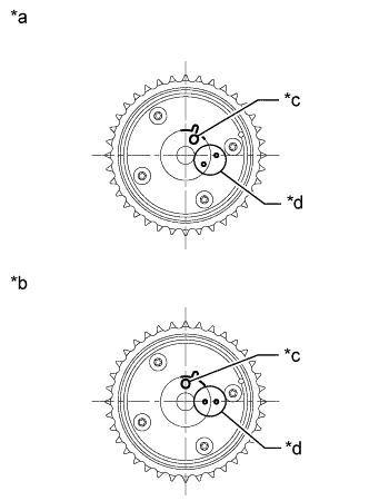
Text in Illustration *a Lock Pin Released *b Lock Pin Locked *c Pin Hole *d Lock Check Point Make sure that the camshaft timing gear assembly is locked.
-
-
Release the lock pin.
-
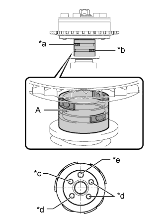
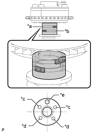
Text in Illustration *a Retard Side Path *b Advance Side Path *c Open *d Close *e Knock Pin 
Rubber Piece 
Vinyl Tape Clean the camshaft journal with non-residue solvent.
-
Cover the 4 oil paths of the cam journal with vinyl tape as shown in the illustration.
Tech Tips
There are 4 oil paths in the grooves of the camshaft. Plug 3 of the paths with pieces of rubber.
-
Open a hole at port A shown in the illustration.
-
While applying approximately 200 kPa (2.0 kgf/cm2, 29 psi) of air pressure to the oil path, forcibly turn the camshaft timing gear assembly in the advance direction (counterclockwise).
Note
-
Cover the paths with a piece of cloth when applying pressure to keep oil from spraying.
-
Do not allow the camshaft timing gear assembly to lock. If it locks, release the lock pin again.
Tech Tips
-
The camshaft timing gear assembly may be turned in the advance direction without applying any force.
-
If enough air pressure cannot be applied because of air leakage from the port, releasing the lock pin may be difficult.
-
-
-
Check for smooth rotation.
-
Turn the camshaft timing gear assembly within its movable range (26.5 to 28.5°) 2 or 3 times, but do not turn it to the most retarded position. Make sure that the gear turns smoothly.
Note
Do not allow the camshaft timing gear assembly to lock. If it locks, release the lock pin again.
-
-
Remove the vinyl tape and rubber pieces from the camshaft.
-
Remove the bolt and camshaft timing gear assembly Click here.
-
Place the chain sub-assembly around the camshaft timing gear assembly.
-
Inspect the camshaft timing gear assembly diameter.
-

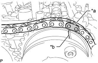
Text in Illustration *a Chain Roller Using a vernier caliper, measure the camshaft timing gear assembly diameter with the chain sub-assembly.
Minimum diameter (with chain sub-assembly) 115.12 mm (4.53 in.) Tech Tips
The vernier caliper must contact the chain rollers for the measurement.
If the diameter is less than the minimum, replace the chain sub-assembly and camshaft timing gear assembly.
-
-
-
INSTALL CAMSHAFT TIMING GEAR ASSEMBLY
Tech Tips
Perform "Inspection After Repair" after replacing the camshaft timing gear assembly.
-
w/ EGR System: Click here
-
w/o EGR System: Click here
-
When using a new camshaft timing gear assembly:
-
Text in Illustration *a Lock Pin Released *b Lock Pin Locked *c Pin Hole *d Lock Check Point Check that the camshaft timing gear assembly is not locked.
Note
If locked, release the lock pin of the camshaft timing gear assembly Click here.
-
-
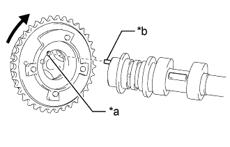
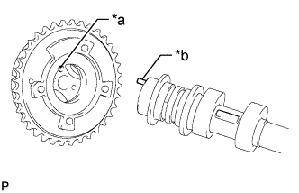
Text in Illustration *a Pin Hole *b Knock Pin When reusing the camshaft timing gear assembly:
-
Release the lock pin Click here.
-
-
Put the camshaft timing gear assembly and camshaft together by aligning the pin hole and knock pin.
-
Lightly press and turn the camshaft timing gear assembly against the camshaft, and press harder after the knock pin enters the pin hole.
Note
-
Be sure not to turn the camshaft timing gear assembly in the advanced direction.
-
Do not forcefully press the camshaft timing gear assembly. Otherwise, the tip of knock pin of the camshaft may damage the seal surface of the camshaft timing gear assembly, leading to poor sealing.
-
-

Text in Illustration *1 Camshaft Timing Gear Assembly *a Incorrect *b Correct *c Clearance *d No Clearance *e Camshaft Flange Check that there is no clearance between the camshaft timing gear assembly and camshaft flange.
-
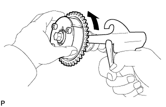
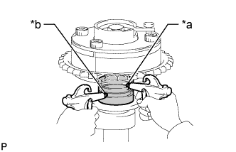
Text in Illustration *a Hold *b Turn Using a wrench to hold the hexagonal portion of the camshaft, tighten the bolt.
- Torque:
- 85 N*m { 867 kgf*cm, 63 ft.*lbf }
Note
-
Be careful not to damage the camshaft housing sub-assembly or spark plug tube with the wrench.
-
If the camshaft timing gear assembly has been locked at the most retarded position, release the lock pin first, and then tighten the bolt.
-
The lock pin may be damaged if the bolt is tightened when the camshaft timing gear assembly is locked.
-
-
INSPECT CAMSHAFT TIMING EXHAUST GEAR ASSEMBLY
-
Secure the No. 2 camshaft between aluminum plates in a vise.
Note
Do not damage the No. 2 camshaft.
-
Install the camshaft timing exhaust gear assembly to the No. 2 camshaft Click here.
-
Release the lock pin.
-
Text in Illustration *a Advance Side Path *b Retard Side Path *c Open *d Close *e Knock Pin Rubber Piece Vinyl Tape Clean the No. 2 camshaft journal with non-residue solvent.
-
Cover the 4 oil paths of the cam journal with vinyl tape as shown in the illustration.
Tech Tips
There are 4 oil paths in the grooves of the No. 2 camshaft. Plug 2 paths with rubber pieces.
-
Make a hole in the vinyl tape placed over the 2 oil holes that are not plugged with rubber pieces.
-
Text in Illustration *a Advance Side Path *b Retard Side Path Apply approximately 200 kPa (2.0 kgf/cm2, 29 psi) of air pressure to the 2 open paths (the advance side path and retard side path).
Note
Cover the paths with a piece of cloth when applying pressure to keep oil from spraying.
-

Text in Illustration *a Advance Side Path *b Retard Side Path *c Hold Pressure *d Decompress Check that the camshaft timing exhaust gear assembly turns in the retard direction when reducing the air pressure applied to the advance side path.
Tech Tips
The lock pin is released and the camshaft timing exhaust gear assembly turns in the retard direction.
-
When the camshaft timing exhaust gear assembly moves to the most retarded position, release the air pressure from the advance side path, and then release the air pressure from the retard side path.
Note
Be sure to release the air pressure from the advance side path first. If the air pressure of the retard side path is released first, the camshaft timing exhaust gear assembly may abruptly shift in the advance direction and break the lock pin or other parts.
-
-
Check for smooth rotation.
-
Turn the camshaft timing exhaust gear assembly within its movable range (21.5 to 23.5°) 2 or 3 times, but do not turn it to the most advanced position. Make sure that the gear turns smoothly.
Note
When the air pressure is released from the advance side path and then from the retard side path, the gear automatically returns to the most advanced position due to the advance assist spring operation, and locks. Gradually release the air pressure from the retard side path before performing the smooth rotation check.
-
-
Remove the vinyl tape and rubber pieces from the No. 2 camshaft.
-
Remove the bolt and camshaft timing exhaust gear assembly Click here.
-
Place the chain sub-assembly around the camshaft timing exhaust gear assembly.
-
Inspect the camshaft timing exhaust gear assembly diameter.
-

Text in Illustration *a Chain Roller Using a vernier caliper, measure the camshaft timing exhaust gear assembly diameter with the chain sub-assembly.
Minimum diameter (with chain sub-assembly) 115.12 mm (4.53 in.) Tech Tips
The vernier caliper must contact the chain rollers for the measurement.
If the diameter is less than the minimum, replace the chain sub-assembly and camshaft timing exhaust gear assembly.
-
-
-
INSTALL CAMSHAFT TIMING EXHAUST GEAR ASSEMBLY
Tech Tips
Perform "Inspection After Repair" after replacing the camshaft timing exhaust gear assembly.
-
w/ EGR System: Click here
-
w/o EGR System: Click here
-
Text in Illustration *a Pin Hole *b Knock Pin Align and attach the knock pin of the No. 2 camshaft with the pin hole of the camshaft timing exhaust gear assembly.
Note
Do not forcefully press the camshaft timing exhaust gear assembly. Otherwise, the tip of knock pin of the No. 2 camshaft may damage the seal surface of the camshaft timing exhaust gear assembly, leading to poor sealing.
-
Text in Illustration *1 Camshaft Timing Exhaust Gear Assembly *a Incorrect *b Correct *c Clearance *d No Clearance *e Camshaft Flange Check that there is no clearance between the camshaft timing exhaust gear assembly and camshaft flange.
-

Text in Illustration *a Hold *b Turn Using a wrench to hold the hexagonal portion of the No. 2 camshaft, tighten the bolt.
- Torque:
- 85 N*m { 867 kgf*cm, 63 ft.*lbf }
Note
Be careful not to damage the camshaft housing sub-assembly or spark plug tube with the wrench.
-
-
POUR ENGINE OIL
Note
-
Oil must be added if the valve lash adjuster assemblies or No. 1 valve rocker arm sub-assemblies were removed.
-
Make sure that the oil passage is full of engine oil.
-

Pour 100 cc (6.1 cu. in.) of engine oil into the oil hole shown in the illustration.
-
-
INSTALL NO. 1 CHAIN VIBRATION DAMPER
-

Install the No. 1 chain vibration damper by tightening the 2 bolts in the order shown in the illustration.
- Torque:
- 21 N*m { 214 kgf*cm, 15 ft.*lbf }
-
-
INSTALL CHAIN SUB-ASSEMBLY
-
Temporarily install the crankshaft pulley set bolt.
-

Rotate the crankshaft 40° counterclockwise.
-
Text in Illustration *a Timing Mark *b Identification Groove *c Approximately 7° *d Approximately 32° Check that the timing marks of the camshaft timing gears are as shown in the illustration.
Tech Tips
The camshaft timing gear assembly and the camshaft timing exhaust gear assembly have both timing marks and identification grooves. Use the timing marks for alignment.
-
Place the chain sub-assembly onto the camshaft timing gears and crankshaft timing gear or sprocket.
Note
-
Make sure the mark plate of the chain sub-assembly faces away front of the engine.
-
It is not necessary to install the chain sub-assembly to the teeth of the camshaft timing gears and crankshaft timing gear or sprocket.
-
-
Text in Illustration *a Mark Plate (Orange) *b Timing Mark Align the mark plate (orange) of the chain sub-assembly with the timing mark of the camshaft timing exhaust gear assembly and install the chain sub-assembly to the camshaft timing exhaust gear assembly.
-

Text in Illustration *a Mark Plate (Yellow) *b Timing Mark Align the mark plate (yellow) of the chain sub-assembly with the timing mark of the crankshaft timing gear or sprocket and install the chain sub-assembly to the crankshaft timing gear or sprocket.
-
Text in Illustration *a String Tie the chain sub-assembly with a string above the crankshaft timing gear or sprocket to secure the chain sub-assembly.
-
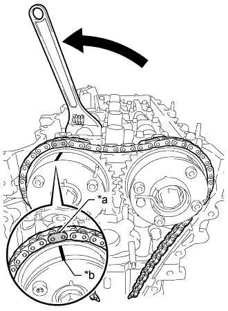
Text in Illustration *a Mark Plate (Orange) *b Timing Mark Using the hexagonal portion of the camshaft, rotate the camshaft counterclockwise with a wrench.
Align the timing mark of the camshaft timing gear assembly with the mark plate (orange) of the chain sub-assembly and install the chain sub-assembly to the camshaft timing gear assembly.
Tech Tips
Hold the camshaft in place with a wrench until the No. 1 chain tensioner assembly is installed.
-
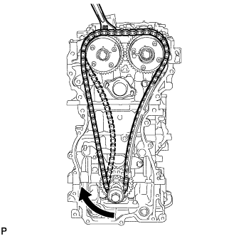
Remove the string above the crankshaft timing gear or sprocket, rotate the crankshaft clockwise, and loosen the chain sub-assembly so that the chain tensioner slipper can be installed.
Note
Make sure that the chain sub-assembly is securely installed.
-
-
INSTALL CHAIN TENSIONER SLIPPER
-
Install the chain tensioner slipper with the bolt.
- Torque:
- 21 N*m { 214 kgf*cm, 15 ft.*lbf }
-
-
INSTALL NO. 1 CHAIN TENSIONER ASSEMBLY
-
Install a new chain tensioner gasket and the No. 1 chain tensioner assembly with the 2 bolts.
- Torque:
- 10 N*m { 102 kgf*cm, 7 ft.*lbf }
-
Remove the pin from the stopper plate.
-
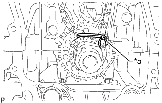
Text in Illustration *a Lock Pin Released *b Lock Pin Locked *c Pin Hole *d Lock Check Point Rotate the camshaft counterclockwise, and then check that the camshaft timing gear assembly locks at the most retarded position.
Note
If the camshaft timing gear assembly is not locked, make sure to lock it securely.
-
-
INSTALL TIMING CHAIN GUIDE
-
Install the timing chain guide with the bolt.
- Torque:
- 21 N*m { 214 kgf*cm, 15 ft.*lbf }
-
-
CHECK NO. 1 CYLINDER TO TDC/COMPRESSION
-
Temporarily install the crankshaft pulley set bolt.
-
Rotate the crankshaft clockwise so that the timing marks on the crankshaft timing gear or sprocket and camshaft timing gears are positioned as shown in the illustration.
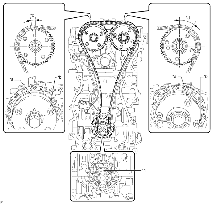
Text in Illustration *1 Crankshaft Pulley Set Crankshaft Key - - *a Timing Mark *b Identification Groove *c Approximately 7° *d Approximately 32° Tech Tips
-
The camshaft timing gear assembly and the camshaft timing exhaust gear assembly have both timing marks and identification grooves. Use the timing marks for alignment.
-
If the timing marks do not align, rotate the crankshaft clockwise again and align the timing marks.
-
-
Remove the crankshaft pulley set bolt.
-
-
INSTALL TIMING CHAIN COVER ASSEMBLY