CAMSHAFT REMOVAL

-
REMOVE TIMING CHAIN COVER ASSEMBLY
-
SET NO. 1 CYLINDER TO TDC/COMPRESSION
-
Temporarily install the crankshaft pulley set bolt.
-
Rotate the crankshaft clockwise so that the timing marks on the crankshaft timing gear or sprocket and camshaft timing gears are positioned as shown in the illustration.
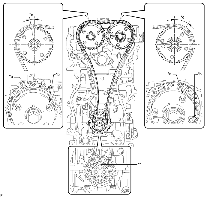
Text in Illustration *1 Crankshaft Pulley Set Crankshaft Key - - *a Timing Mark *b Identification Groove *c Approximately 7° *d Approximately 32° Tech Tips
-
The camshaft timing gear assembly and the camshaft timing exhaust gear assembly have both timing marks and identification grooves. Use the timing marks for alignment.
-
If the timing marks do not align, rotate the crankshaft clockwise again and align the timing marks.
-
-
Remove the crankshaft pulley set bolt.
-
-
REMOVE TIMING CHAIN GUIDE
-
Remove the bolt and timing chain guide.
-
-
REMOVE NO. 1 CHAIN TENSIONER ASSEMBLY
-
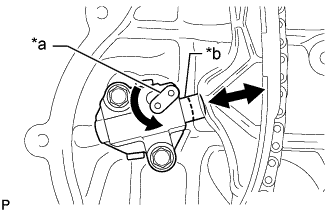
Text in Illustration *a Stopper Plate *b Plunger Allow the plunger to extend slightly, and then rotate the stopper plate counterclockwise to release the lock. Once the lock is released, push the plunger into the tensioner.
-
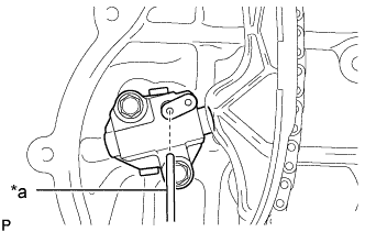
Text in Illustration *a Pin Move the stopper plate clockwise to set the lock, and insert a pin into the stopper plate hole.
-
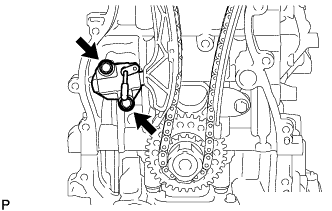
Remove the 2 bolts, No. 1 chain tensioner assembly and chain tensioner gasket.
-
-
REMOVE CHAIN TENSIONER SLIPPER
-
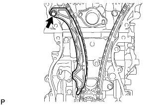
Remove the bolt and chain tensioner slipper.
-
-
REMOVE NO. 1 CHAIN VIBRATION DAMPER
-
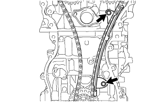
Remove the 2 bolts and No. 1 chain vibration damper.
-
-
REMOVE CHAIN SUB-ASSEMBLY
-
Remove the chain sub-assembly.
-
-
REMOVE CAMSHAFT TIMING GEAR ASSEMBLY
-
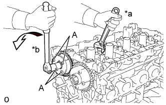
Text in Illustration *a Hold *b Turn Hold the hexagonal portion of the camshaft with a wrench and remove the bolt and camshaft timing gear assembly.
Note
-
Never remove the 4 bolts (A). If they are removed, make sure to replace the camshaft timing gear assembly.
-
Be careful not to damage the camshaft housing sub-assembly or spark plug tube with the wrench.
-
-
Remove the camshaft timing gear assembly from the camshaft.
-
-
REMOVE CAMSHAFT TIMING EXHAUST GEAR ASSEMBLY
-
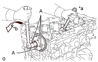
Text in Illustration *a Hold *b Turn Hold the hexagonal portion of the No. 2 camshaft with a wrench and remove the bolt and camshaft timing exhaust gear assembly.
Note
-
Never remove the 4 bolts (A). If they are removed, make sure to replace the camshaft timing exhaust gear assembly.
-
Be careful not to damage the camshaft housing sub-assembly or spark plug tube with the wrench.
-
-
Remove the camshaft timing exhaust gear assembly from the No. 2 camshaft.
-
-
REMOVE CAMSHAFT HOUSING SUB-ASSEMBLY
-
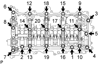
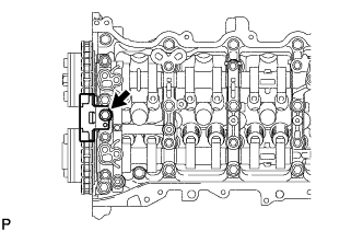
Uniformly loosen and remove the 20 bolts in the sequence shown in the illustration.
-
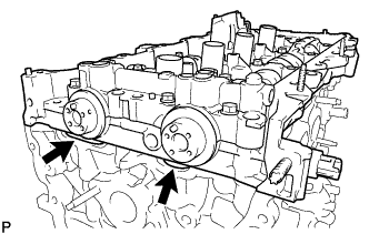
Remove the camshaft housing sub-assembly by prying between the cylinder head sub-assembly and camshaft housing sub-assembly with a screwdriver.
Note
Be careful not to damage the contact surfaces of the cylinder head sub-assembly and camshaft housing sub-assembly.
Tech Tips
Tape the screwdriver tip before use.
-
-
REMOVE CAMSHAFT BEARING CAP
-
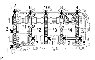
Text in Illustration *1 No. 1 Camshaft Bearing Cap *2 No. 2 Camshaft Bearing Cap *3 No. 3 Camshaft Bearing Cap *4 No. 4 Camshaft Bearing Cap Uniformly loosen and remove the 11 bolts in the sequence shown in the illustration.
-
Remove the No. 1 camshaft bearing cap, No. 2 camshaft bearing cap, No. 3 camshaft bearing cap and No. 4 camshaft bearing cap.
-
-
REMOVE OIL CONTROL VALVE FILTER
-
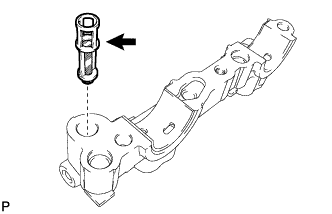
Remove the oil control valve filter from the No. 1 camshaft bearing cap.
Note
Do not touch the mesh section on the oil control valve filter.
-
-
REMOVE NO. 1 CAMSHAFT BEARING
-
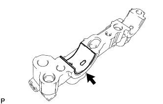
Remove the No. 1 camshaft bearing from the No. 1 camshaft bearing cap.
-
-
REMOVE CAMSHAFT
-
Remove the camshaft from the camshaft housing sub-assembly.
-
-
REMOVE NO. 2 CAMSHAFT
-
Remove the No. 2 camshaft from the camshaft housing sub-assembly.
-
-
REMOVE NO. 2 CAMSHAFT BEARING
-
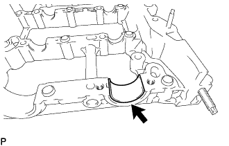
Remove the No. 2 camshaft bearing from the camshaft housing sub-assembly.
-
-
REMOVE NO. 1 VALVE ROCKER ARM SUB-ASSEMBLY
-
Remove the 16 No. 1 valve rocker arm sub-assemblies from the cylinder head sub-assembly.
Tech Tips
Be sure to keep the removed parts for each installation position separate.
-
-
REMOVE VALVE LASH ADJUSTER ASSEMBLY
-
Remove the 16 valve lash adjuster assemblies from the cylinder head sub-assembly.
Tech Tips
Be sure to keep the removed parts for each installation position separate.
-