DRIVE BELT INSTALLATION

-
INSTALL FAN AND GENERATOR V BELT
Tech Tips
When reusing the fan and generator V belt, check the ribs and back of the fan and generator V belt for wear and cracks. If wear or a crack that reaches the core (at more than 1 point) is found, replace the fan and generator V belt.
-
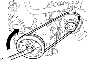
Partially mount the fan and generator V belt on the engine water pump assembly as shown in the illustration. Mount the fan and generator V belt around the engine water pump assembly partially as shown in the illustration.
Note
-
Make sure the fan and generator V belt is securely mounted on the crankshaft pulley assembly.
-
Do not allow slack in the fan and generator V belt.
-
-
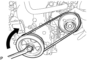
While holding the fan and generator V belt on the engine water pump assembly by hand as shown in the illustration, gradually rotate the crankshaft pulley assembly clockwise to mount the fan and generator V belt on the engine water pump assembly.
CAUTION:
Do not hold any other parts of the fan and generator V belt, or your fingers may get caught between the fan and generator V belt and engine water pump assembly as they are rotated.
Note
-
Guide the fan and generator V belt into the grooves of the engine water pump assembly as the crankshaft pulley assembly is rotated.
-
Make sure the fan and generator V belt is not inside out.
-
-
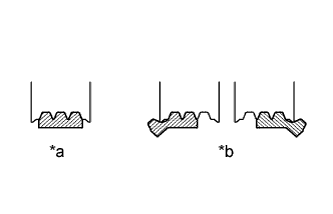
Text in Illustration *a Correct *b Incorrect Rotate the crankshaft pulley assembly until the fan and generator V belt is fully mounted on the engine water pump assembly.
-
Check that the fan and generator V belt is securely mounted on the crankshaft pulley assembly and engine water pump assembly.
Note
Make sure the ribs of the fan and generator V belt are not cracked.
-
Start the engine and check that the fan and generator V belt turns smoothly without any noise.
-
-
INSTALL NO. 1 ENGINE COVER SUB-ASSEMBLY
-
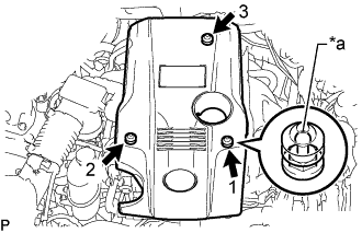
Text in Illustration *a Tip (Round Portion) Attach the 3 clips in the order shown in the illustration to install the No. 1 engine cover sub-assembly.
Note
-
Securely engage the clips.
-
If the clips are forcibly attached or struck with an object, they may be damaged.
-
-
-
INSTALL NO. 1 AIR CLEANER INLET
-
Install the No. 1 air cleaner inlet with the bolt.
- Torque:
- 5.0 N*m { 51 kgf*cm, 44 in.*lbf }
-
-
INSTALL COOL AIR INTAKE DUCT SEAL
-
Install the cool air intake duct seal with the 7 clips.
-
-
INSTALL ENGINE ROOM SIDE COVER
-
Install the engine room side cover with the 4 clips.
-