DRIVE BELT REMOVAL

-
REMOVE ENGINE ROOM SIDE COVER
-
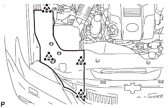
Remove the 4 clips and engine room side cover.
-
-
REMOVE COOL AIR INTAKE DUCT SEAL
-
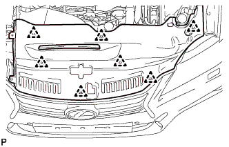
Remove the 7 clips and cool air intake duct seal.
-
-
REMOVE NO. 1 AIR CLEANER INLET
-
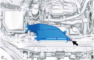
Remove the bolt and No. 1 air cleaner inlet.
-
-
REMOVE NO. 1 ENGINE COVER SUB-ASSEMBLY
-
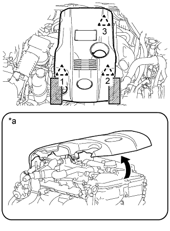
Text in Illustration *a When detaching the clip on the rear side of the cover 
Areas to be held when lifting the No. 1 engine cover sub-assembly Place both hands on either side of the No. 1 engine cover sub-assembly as shown in the illustration and detach the left and right side clips (1 and 2) near the front of the cover. Then, lift up the cover to detach the clip (3) on the rear side and remove the cover.
Note
-
If the left and right sides and front and back sides of the cover are lifted up at the same time, the cover may be damaged.
-
If the procedures are not followed exactly, the clip on the rear side of the cover may be damaged.
-
If you attempt to remove the cover with only one of the front clips detached, the cover may be damaged.
-
-
-
REMOVE FAN AND GENERATOR V BELT
-
Prepare a clean durable piece of cloth and fold it several times.
Tech Tips
Fold the cloth several times to make it thicker.
-
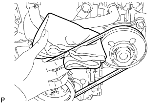
Pass the cloth under the fan and generator V belt between the crankshaft pulley assembly and engine water pump assembly as shown in the illustration.
Note
Position the cloth so that the part closest to the engine is longer.
-
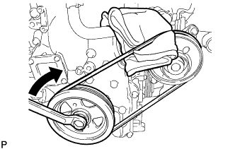
Slightly rotate the crankshaft pulley assembly clockwise so that the cloth is pulled between the fan and generator V belt and engine water pump assembly.
Note
Do not allow the cloth to be pulled further than the top center of the engine water pump assembly.
-
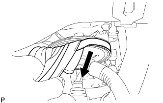
Fold the cloth over the fan and generator V belt and pull it as shown in the illustration while gradually rotating the crankshaft pulley assembly clockwise.
Note
Pull the cloth until the upper part of the fan and generator V belt comes off the engine water pump assembly.
-
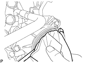
Check that the upper part of the fan and generator V belt is off the engine water pump assembly, then rotate the crankshaft pulley assembly clockwise to remove the fan and generator V belt.
-