HV RELAY ASSEMBLY INSTALLATION

-
INSTALL HYBRID BATTERY JUNCTION BLOCK ASSEMBLY
CAUTION:
Perform work using insulated gloves and insulated tools.
Note
If the hybrid battery junction block assembly has been dropped, replace it with a new one.
-
Install the hybrid battery junction block assembly with the 3 nuts.
- Torque:
- 7.5 N*m { 76 kgf*cm, 66 in.*lbf }
-
Connect the 5 connectors.
-
-
INSTALL UPPER HYBRID BATTERY COVER SUB-ASSEMBLY
CAUTION:
Perform work using insulated gloves and insulated tools.
-
Install the upper hybrid battery cover sub-assembly together with the power steering converter wire with the 11 nuts.
- Torque:
- 7.5 N*m { 76 kgf*cm, 66 in.*lbf }
-
Attach the 3 wire harness clamps to connect the No. 2 hybrid battery pack wire.
-
-
INSTALL REAR NO. 1 HYBRID BATTERY SHIELD
CAUTION:
Perform work using insulated gloves and insulated tools.
-
Install the rear No. 1 hybrid battery shield with the 3 nuts and 2 bolts.
- Torque:
- 7.5 N*m { 76 kgf*cm, 66 in.*lbf }
-
Attach the wire harness clamp and connect the connector.
-
-
INSTALL BATTERY COOLING BLOWER ASSEMBLY
CAUTION:
Perform work using insulated gloves and insulated tools.
-
Install the battery cooling blower assembly with the 3 nuts.
- Torque:
- 7.5 N*m { 76 kgf*cm, 66 in.*lbf }
Note
-
Hold the wire harness and fan, and do not install them.
-
Make sure that foreign matter does not enter the battery cooling blower assembly.
-
Connect the connector.
-
Attach the wire harness clamp and connect the connector.
-
-
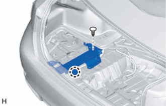
INSTALL VOLTAGE INVERTER ASSEMBLY (w/ Voltage Inverter)
-
for 2AR-FSE:
-
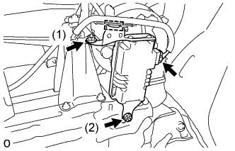
Set the voltage inverter assembly in place.
-
Temporarily install the 2 nuts.
-
Tighten the 2 nuts in the order shown in the illustration.
- Torque:
- 8.0 N*m { 82 kgf*cm, 71 in.*lbf }
-
Connect the connector and attach the clamp.
-
-
for 2GR-FXE:
-
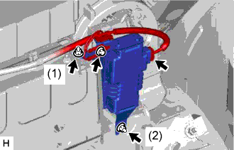
Set the voltage inverter assembly in place.
-
Temporarily install the 2 nuts.
-
Tighten the 2 nuts in the order shown in the illustration.
- Torque:
- 8.0 N*m { 82 kgf*cm, 71 in.*lbf }
-
Connect the wire harness with the bolt.
-
Connect the connector.
-
-
-
INSTALL POWER STEERING CONVERTER ASSEMBLY
CAUTION:
Perform work using insulated gloves and insulated tools.
-
Install the power steering converter assembly with the 3 nuts.
- Torque:
- 8.5 N*m { 87 kgf*cm, 75 in.*lbf }
-
Connect the 2 wire harnesses with the 2 bolts.
- Torque:
- 8.5 N*m { 87 kgf*cm, 75 in.*lbf }
-
Connect the 4 connectors.
-
-
INSTALL ECU BRACKET
CAUTION:
Perform work using insulated gloves and insulated tools.
-
Install the ECU bracket with the 2 nuts.
- Torque:
- 8.5 N*m { 87 kgf*cm, 75 in.*lbf }
-
-
INSTALL NO. 3 HYBRID BATTERY INTAKE DUCT
-
Install the No. 3 hybrid battery intake duct to the No. 4 hybrid battery intake duct with the clip.
-
-
INSTALL BRAKE CONTROL POWER SUPPLY ASSEMBLY
-
Connect the connector.
-
Hook and the claws of the No. 1 brake control power supply bracket to the body to set it in place.
-
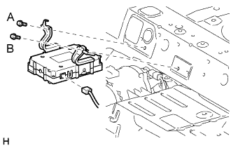
Install the brake control power supply assembly with the 2 bolts.
- Torque:
- 14 N*m { 138 kgf*cm, 10 ft.*lbf }
Note
Install the bolts in alphabetical order.
-
-
INSTALL NO. 6 HYBRID BATTERY INTAKE DUCT
-
Install the No. 6 hybrid battery intake duct with the 2 clips.
-
-
INSTALL NO. 1 HYBRID BATTERY INTAKE DUCT
-
Install the No. 1 hybrid battery intake duct with the 2 clips.
-
-
CONNECT NO. 4 FLOOR WIRE
CAUTION:
Perform work using insulated gloves and insulated tools.
-
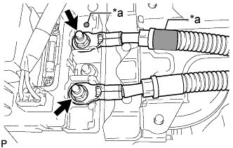
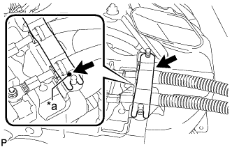
Text in Illustration *a Matchmark Connect the 2 No. 4 floor wires with the 2 nuts.
Note
Be sure to match the red marks on the No. 4 floor wire to the red marks on the hybrid battery junction block assembly and connect the No. 4 floor wire.
- Torque:
- 9.0 N*m { 92 kgf*cm, 80 in.*lbf }
-
Text in Illustration *a Matchmark Install the battery shield contact.
Note
Align the matchmark when installing the battery shield contact.
-
-
CHECK HIGH VOLTAGE CABLE CONNECTION CONDITION
CAUTION:
Wear insulated gloves and protective goggles.
-
Check that each wire harness is being installed securely.
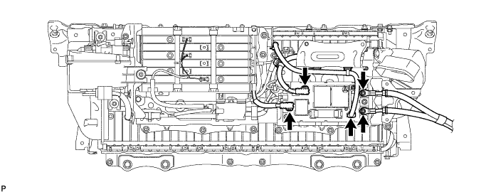
Text in Illustration *1 No. 4 Floor Wire - - Note
-
Make sure that the ends of the frame wire are not crossed over each other.
-
Be sure to connect the frame wire to the correct terminals as shown in the illustration.
-
The connectors should be connected securely.
-
The nuts should be fastened securely.
-
Make sure that the 2 plastic covers are engaged securely.
-
-
-
INSTALL NO. 4 HYBRID VEHICLE BATTERY SHIELD SUB-ASSEMBLY
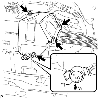
Text in Illustration *1 Button *a Push CAUTION:
Perform work using insulated gloves and insulated tools.
-
Set the No. 4 hybrid vehicle battery shield sub-assembly in place and temporarily install the 4 nuts.
-
Insert the battery cover lock striker and then push the button to lock it.
-
Tighten the 4 nuts.
- Torque:
- 8.0 N*m { 82 kgf*cm, 71 in.*lbf }
-
-
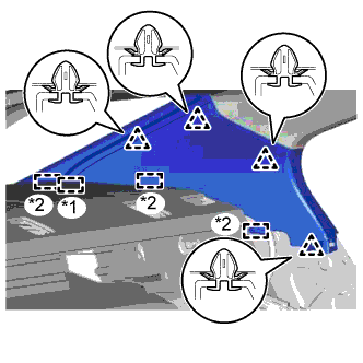
INSTALL INNER LUGGAGE COMPARTMENT TRIM COVER LH
-
Attach the clip to install the luggage compartment trim inner cover LH.
-
Attach the 2 claws to install the clip.
-
Install the clip.
-
-
INSTALL INNER LUGGAGE COMPARTMENT TRIM COVER RH
-
Attach the clip to install the luggage compartment trim inner cover RH.
-
Attach the 2 claws to install the clip.
-
Install the clip.
-
-
INSTALL ROPE HOOK
Tech Tips
Use the same procedure for both rope hooks
-
Install the rope hook.
-
-
INSTALL FRONT LUGGAGE COMPARTMENT TRIM COVER
-
Install the front luggage compartment trim cover with the 3 clips and 2 nuts.
-
-
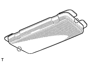
INSTALL REAR FLOOR FINISH PLATE
-
Attach the 6 clips to install the rear floor finish plate.
-
Install the 3 clips.
-
-
INSTALL REAR LUGGAGE COMPARTMENT TRIM COVER
-
Attach the 3 guides to install the rear luggage compartment trim cover
-
Install the 5 clips.
-
Install the 3 No. 2 luggage compartment trim hooks.
-
-
INSTALL NO. 1 LUGGAGE COMPARTMENT LIGHT ASSEMBLY
-
Connect the connector.
-
Attach the 2 claws to install the No. 1 luggage compartment light assembly.
-
-
INSTALL NO. 1 LUGGAGE COMPARTMENT TRIM HOOK
-
Attach the 2 claws to install the No. 1 luggage compartment trim hook.
-
-
INSTALL REAR LUGGAGE COMPARTMENT TRAY BRACKET LH
-
Remove the clip.
-
Detach the claw and remove the rear luggage compartment tray bracket LH.
-
-
INSTALL REAR LUGGAGE COMPARTMENT TRAY BRACKET RH
Tech Tips
Use the same procedure described for the LH side.
-
INSTALL ROPE HOOK ASSEMBLY
Tech Tips
Use the same procedure for all rope hooks.
-
Install the rope hook assembly with the bolt.
-
Attach the 2 claws to close the cover.
-
-
INSTALL LUGGAGE COMPARTMENT SIDE TRAY (w/ Spare Tire)
-
Install the luggage compartment side tray.
-
-
INSTALL SPARE WHEEL COVER TRAY (w/o Spare Tire)
-
Install the spare wheel cover tray.
-
-
INSTALL LUGGAGE COMPARTMENT TRIM BOX (w/o Spare Tire)
-
Install the luggage compartment trim box.
-
-
INSTALL SIDE TRIM BOX
-
Install the side trim box.
-
-
INSTALL LUGGAGE COMPARTMENT TRIM COVER RH
-
Install the luggage compartment trim cover RH.
-
-
INSTALL NO. 1 ROOM PARTITION PAD
-
Install the No. 1 room partition pad with the 5 clips.
-
-
INSTALL NO. 2 ROOM PARTITION PAD
-
Install the No. 2 room partition pad with the 2 clips.
-
-
INSTALL NO. 2 PACKAGE TRAY TRIM PANEL ASSEMBLY (w/ Rear Sunshade)
-
Attach the 5 guides and 3 clips to install the No. 2 package tray trim panel assembly.
-
-
INSTALL CENTER STOP LIGHT COVER (w/ Rear Sunshade)
-
Connect the connector.
-
Attach the 4 claws to install the center stop light cover.
-
-
INSTALL PACKAGE TRAY TRIM PANEL ASSEMBLY
-
w/o Rear Sunshade:
-
Pass the 3 rear seat belt floor anchors through the package tray trim panel assembly.
-
Insert the package tray trim panel assembly into the 5 guides and attach the 4 clips to install the package tray trim panel assembly.
-
Connect the connector.
-
Attach the 4 claws to install the center stop light cover.
-
-
w/ Rear Sunshade:
-
Pass the 3 rear seat belt floor anchors through the package tray trim panel assembly.
-
Insert the package tray trim panel assembly into the rear window shade assembly and attach the 4 clips to install the package tray trim panel assembly.
-
-
Attach the 4 claws to install the belt guide of rear seat inner with center belt assembly LH to the package tray trim panel assembly.
-
Attach the 4 claws to install the rear seat shoulder belt hole cover to the package tray trim panel assembly.
Tech Tips
Use the same procedure to install the rear seat shoulder belt hole cover on the other side.
-
-
INSTALL INNER ROOF SIDE GARNISH LH
Text in Illustration *1 End Of The Rear Window Shade Assembly *2 Guide
-
w/ Rear Sunshade:
-
Insert the rear window shade assembly and attach the 3 guides.
-
Attach the 4 clips to install the inner roof side garnish LH.
Note
After installing the inner roof side garnish LH, make sure that the lip of the rear door opening trim weatherstrip LH is not pinched.
-
-
w/o Rear Sunshade:
-
Attach the 4 clips and 3 guides to install the inner roof side garnish LH.
Note
After installing the inner roof side garnish LH, make sure that the lip of the rear door opening trim weatherstrip LH is not pinched.
-
-
-
INSTALL REAR SEAT SIDE GARNISH LH
-
Attach the 4 claws and guide to install the rear seat side garnish LH.
Note
After installing the rear seat side garnish LH, make sure that the lip of the rear door opening trim weatherstrip LH is not pinched.
-
-
INSTALL REAR DOOR SCUFF PLATE LH
-
Attach the 10 claws and 3 clips to install the rear door scuff plate LH.
-
-
INSTALL INNER ROOF SIDE GARNISH RH
Tech Tips
Use the same procedure described for the LH side.
-
INSTALL REAR SEAT SIDE GARNISH RH
Tech Tips
Use the same procedure described for the LH side.
-
INSTALL REAR DOOR SCUFF PLATE RH
Tech Tips
Use the same procedure described for the LH side.
-
INSTALL REAR SEAT ASSEMBLY
-
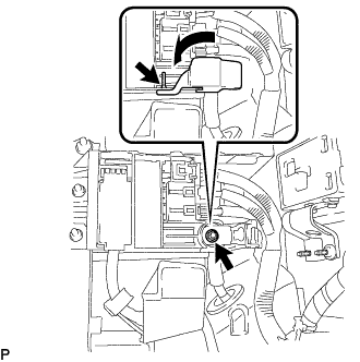
INSTALL SERVICE PLUG GRIP
CAUTION:
Wear insulated gloves.
Note
Before connecting the service plug, check that no parts and tools remain and that the high voltage terminals and connectors are connected securely.
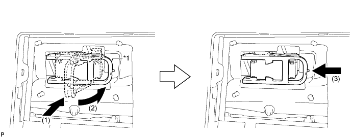
Text in Illustration *1 Lever - -
-
Install the service plug grip in the order shown in the illustration.
-
Insert the service plug grip and rotate the lever.
-
Slide the lever until a click sound is heard to lock the lever.
-
-
-
INSTALL LOWER HYBRID VEHICLE BATTERY COVER PANEL
CAUTION:
Perform work using insulated gloves and insulated tools.
-
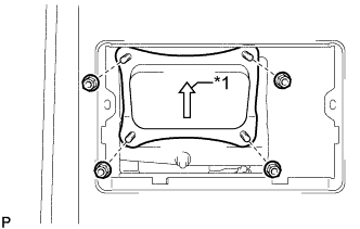
Text in Illustration *1 Arrow Install the lower hybrid vehicle battery cover panel with the 4 nuts.
Tech Tips
Be sure to install the lower hybrid vehicle battery cover panel with its arrow facing upwards.
- Torque:
- 8.0 N*m { 82 kgf*cm, 71 in.*lbf }
-
-
INSTALL NO. 1 SEAT ARMREST CAP
-
Attach the 4 guides and 4 claws to install the No. 1 seat armrest cap.
-
-
CONNECT CABLE TO AUXILIARY BATTERY TERMINAL
Note
When disconnecting the cable some systems need to be initialized after the cable is reconnected Click here.
-
Connect cable to the auxiliary battery positive (+) terminal with the nut.
- Torque:
- 6.8 N*m { 69 kgf*cm, 60 in.*lbf }
-
Install the terminal cover.
-
Connect cable to the auxiliary battery negative (-) terminal.
- Torque:
- 5.5 N*m { 56 kgf*cm, 49 in.*lbf }
-
-
INSTALL LUGGAGE COMPARTMENT TRIM COVER LH
-
Install the luggage compartment trim cover LH.
-
-
INSTALL LUGGAGE COMPARTMENT FLOOR MAT
-
Install the luggage compartment floor mat.
-