ENGINE ASSEMBLY REMOVAL

CAUTION:
The engine assembly with transmission is very heavy. Be sure to follow the procedure described in the repair manual, or the engine lifter may suddenly drop.
-
PRECAUTION
CAUTION:
Be sure to read Precaution thoroughly before servicing Click here.
Note
After turning the power switch off, waiting time may be required before disconnecting the cable from the negative (-) auxiliary battery terminal. Therefore, make sure to read the disconnecting the cable from the negative (-) auxiliary battery terminal notices before proceeding with work Click here.
-
REMOVE ENGINE ROOM SIDE COVER
-
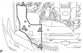
Remove the 4 clips and engine room side cover.
-
-
REMOVE COOL AIR INTAKE DUCT SEAL
-
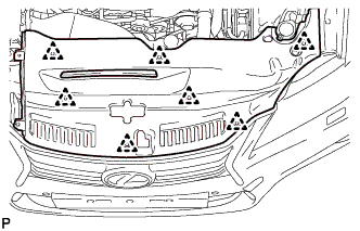
Remove the 7 clips and cool air intake duct seal.
-
-
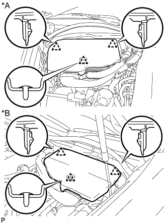
REMOVE NO. 1 ENGINE COVER SUB-ASSEMBLY
-
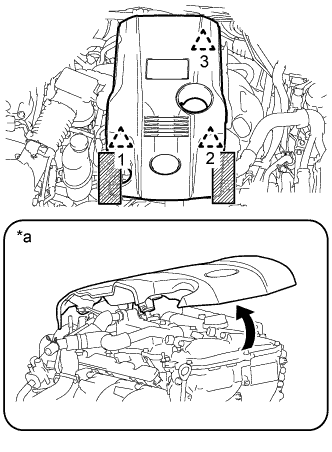
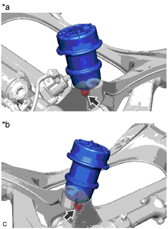
Text in Illustration *a When detaching the clip on the rear side of the cover 
Areas to be held when lifting the No. 1 engine cover sub-assembly Place both hands on either side of the No. 1 engine cover sub-assembly as shown in the illustration and detach the left and right side clips (1 and 2) near the front of the cover. Then, lift up the cover to detach the clip (3) on the rear side and remove the cover.
Note
-
If the left and right sides and front and back sides of the cover are lifted up at the same time, the cover may be damaged.
-
If the procedures are not followed exactly, the clip on the rear side of the cover may be damaged.
-
If you attempt to remove the cover with only one of the front clips detached, the cover may be damaged.
-
-
-
RECOVER REFRIGERANT FROM REFRIGERATION SYSTEM
-
Turn the power switch on (READY).
-
Turn the A/C switch on.
-
Operate the air conditioning with a set temperature of 25°C (77°F) and the blower at low for 10 minutes to circulate the refrigerant. This causes most of the compressor oil from the various components of the air conditioning system to collect in the air conditioning compressor.
-
Turn the power switch off.
-
Recover the refrigerant from the air conditioning system using a refrigerant recovery unit.
-
-
DISCHARGE FUEL SYSTEM PRESSURE
-
PLACE FRONT WHEELS FACING STRAIGHT AHEAD
-
SECURE STEERING WHEEL
-
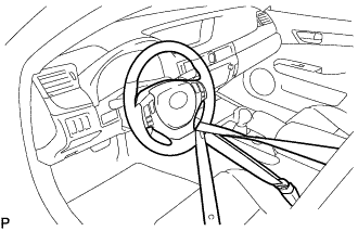
Secure the steering wheel with the seat belt in order to prevent rotation.
Tech Tips
This operation is useful to prevent damage to the spiral cable.
-
-
REMOVE LUGGAGE COMPARTMENT FLOOR MAT
-
Remove the luggage compartment floor mat.
-
-
REMOVE LUGGAGE COMPARTMENT TRIM COVER LH
-
Remove the luggage compartment trim cover LH.
-
-
DISCONNECT CABLE FROM AUXILIARY BATTERY NEGATIVE TERMINAL
Note
When disconnecting the cable, some systems need to be initialized after the cable is reconnected Click here.
-
Disconnect the cable from the auxiliary battery negative (-) terminal.
-
-
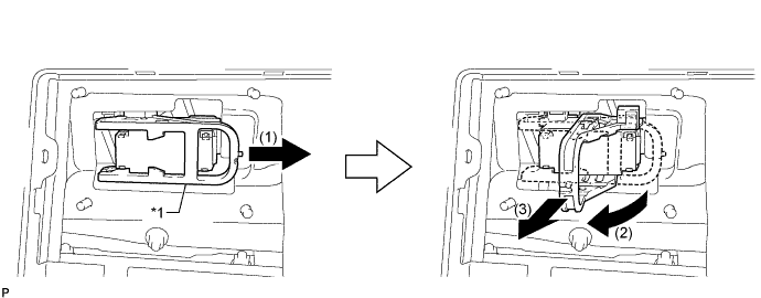
REMOVE NO. 1 SEAT ARMREST CAP
-
Detach the 4 claws and 4 guides, and remove the No. 1 seat armrest cap.
-
-
REMOVE LOWER HYBRID VEHICLE BATTERY COVER PANEL
CAUTION:
Perform work using insulated gloves and insulated tools.
-
Remove the 4 nuts and lower hybrid vehicle battery cover panel.
-
-
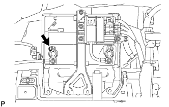
REMOVE SERVICE PLUG GRIP
Text in Illustration *1 Lever - -
-
Remove the service plug grip in the order shown in the illustration.
CAUTION:
-
Wear insulated gloves.
-
Remove the service plug grip to interrupt a high voltage circuit at the time of the check.
-
Keep the removed service plug grip in your pocket to prevent other technicians from accidentally reconnecting it while you are servicing the vehicle.
-
After disconnecting the service plug grip, wait at least 10 minutes before touching any of the high-voltage connectors or terminals.
-
Never turn the power switch on (READY) with the service plug grip removed as malfunctions may occur.
Tech Tips
-
Waiting for at least 10 minutes is required to discharge the high-voltage capacitor inside the inverter with converter assembly.
-
High voltage wiring connectors are orange.
-
Slide the lever and release the lock.
-
Raise the lever and pull the service plug grip to remove it.
-
-
-
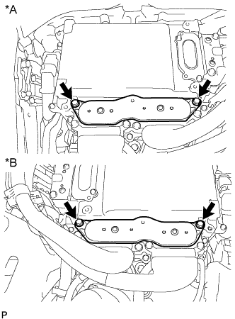
REMOVE INVERTER COVER
-
Text in Illustration *A for LHD *B for RHD Raise the front of the inverter cover to detach the clip. Then remove the 2 inverter cover clips from the bracket, and remove the inverter cover.
-
-
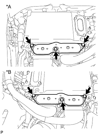
REMOVE CONNECTOR COVER ASSEMBLY
CAUTION:
-
Do not touch the high voltage connectors and terminals for 10 minutes after the service plug grip is removed.
-
Wear insulated gloves.
Note
Do not start the hybrid system with the service plug grip removed because it may cause a malfunction.
-
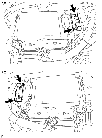
Text in Illustration *A for LHD *B for RHD Using an insulated tool, remove the 2 bolts and connector cover assembly.
Note
-
Make sure to pull the connector cover assembly straight up, as a connector is connected to the bottom of the connector cover assembly.
-
Do not allow any foreign objects or water to enter the inverter with converter assembly.
-
-
-
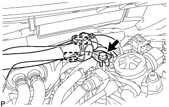
CHECK TERMINAL VOLTAGE
CAUTION:
Wear insulated gloves.
Note
Do not allow any foreign objects or water to enter the inverter with converter assembly.
-
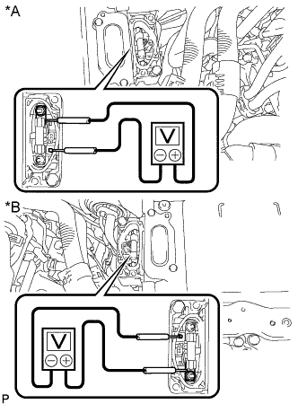
Text in Illustration *A for LHD *B for RHD Using a voltmeter, measure the voltage between the terminals of the 2 phase connectors.
Standard voltage 0 V Tech Tips
Use a measuring range of DC 750 V or more on the voltmeter.
-
-
TEMPORARILY INSTALL CONNECTOR COVER ASSEMBLY
CAUTION:
Wear insulated gloves.
-
Temporarily install the connector cover assembly with the bolt to prevent any foreign objects or water from entering the inverter with converter assembly.
-
-
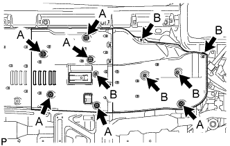
REMOVE ENGINE UNDER COVER
-
Remove the 13 screws, 3 clips and engine under cover.
-
-
REMOVE REAR ENGINE UNDER COVER LH
-
Remove the screw and rear engine under cover LH.
-
-
REMOVE REAR ENGINE UNDER COVER RH
Tech Tips
Use the same procedure described for the LH side.
-
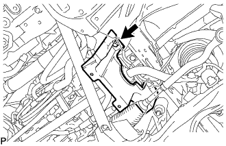
REMOVE FRONT SUSPENSION MEMBER BRACE
-
Remove the 4 bolts, turn the clip to loosen it, and remove the front suspension member brace.
Tech Tips
Do not remove the clip from the front suspension member brace.
-
-
REMOVE NO. 2 ENGINE UNDER COVER
-
Remove the 4 screws, turn the 2 grommets to loosen them and remove the No. 2 engine under cover.
-
-
DRAIN ENGINE OIL
-
Remove the oil filler cap.
-
Remove the oil pan drain plug and gasket, and drain the engine oil into a container.
-
Clean the oil pan drain plug.
-
Install a new gasket to the oil pan drain plug.
-
Install the oil pan drain plug.
- Torque:
- 40 N*m { 408 kgf*cm, 30 ft.*lbf }
-
-
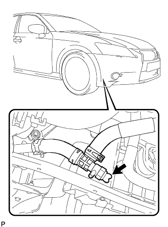
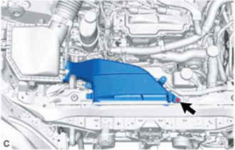
DRAIN ENGINE COOLANT (for Engine)
CAUTION:
Do not remove the water filler cap sub-assembly or reservoir tank cap while the engine and radiator assembly are still hot. Pressurized hot engine coolant and steam may be released and cause serious burns.
-
Remove the 3 screws and No. 4 center engine under cover.
-
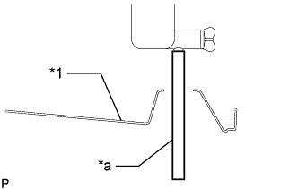
Text in Illustration *1 Engine Under Cover *a Vinyl Tube Install a vinyl tube to the radiator drain cock on the radiator side.
-
Loosen the radiator drain cock sub-assembly.
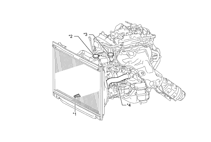
Text in Illustration *1 Radiator Drain Cock Sub-assembly *2 Reservoir Tank Cap *3 Water Filler Cap Sub-assembly *4 No. 2 Radiator Hose Sub-assembly -
Remove the reservoir tank cap and water filler cap sub-assembly. Then drain the engine coolant.
Tech Tips
Collect the engine coolant in a container and dispose of it according to the regulations in your area.
-
-
DRAIN COOLANT (for Inverter)
Note
-
Do not reuse the drained coolant because it may contain foreign objects.
-
Collect the drained coolant and measure its volume to establish a benchmark. When adding coolant, make sure to add more coolant than the measured amount.
-
Remove the reservoir tank cap.
-
Loosen the drain cock plug.
CAUTION:
To avoid the danger of being burned, do not remove the reservoir tank cap while the coolant for the inverter is still hot.
-
-
REMOVE NO. 1 AIR CLEANER INLET
-
Remove the bolt and No. 1 air cleaner inlet.
-
-
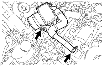
REMOVE AIR CLEANER CAP WITH NO. 2 AIR CLEANER HOSE
-
Disconnect the mass air flow meter sub-assembly connector.
-
Disconnect the wire harness clamp from the air cleaner cap with No. 2 air cleaner hose.
-
Detach the 4 clamps.
-
Loosen the hose clamp to remove the air cleaner cap with No. 2 air cleaner hose.
-
-
REMOVE AIR CLEANER FILTER ELEMENT SUB-ASSEMBLY
-
Remove the air cleaner filter element sub-assembly from the air cleaner case sub-assembly.
-
-
REMOVE AIR CLEANER CASE SUB-ASSEMBLY
-
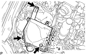
Text in Illustration *a Air Cleaner Support Disconnect the wire harness clamp from the air cleaner case sub-assembly.
-
Remove the 2 bolts and air cleaner case sub-assembly.
Note
Make sure the air cleaner support is attached to the vehicle body.
-
-
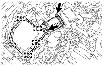
REMOVE AIR CLEANER HOSE ASSEMBLY
-
Slide the clamp and disconnect the ventilation hose from the cylinder head cover sub-assembly.
-
Loosen the hose clamp to remove the air cleaner hose assembly from the throttle body with motor assembly.
-
-
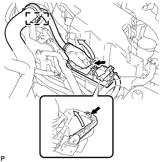
REMOVE INVERTER MOTOR CABLE BRACKET ASSEMBLY
-
Text in Illustration *A for LHD *B for RHD Detach the 2 clamps from the inverter motor cable bracket assembly.
-
Remove the 2 bolts and inverter motor cable bracket assembly.
-
-
REMOVE INVERTER TERMINAL COVER
CAUTION:
Wear insulated gloves.
-
for Type A:
-
Text in Illustration *A for LHD *B for RHD Using an insulated tool, remove the 2 bolts and inverter terminal cover.
Note
-
Make sure to pull the inverter terminal cover straight up, as a connector is connected to the bottom of the inverter terminal cover.
-
Do not touch the inverter terminal cover waterproofing rubber.
-
-
-
for Type B:
-
Text in Illustration *A for LHD *B for RHD Using an insulated tool, remove the 3 bolts and inverter terminal cover.
Note
-
Make sure to pull the inverter terminal cover straight up, as a connector is connected to the bottom of the inverter terminal cover.
-
Do not touch the inverter terminal cover waterproofing rubber.
-
-
-
-
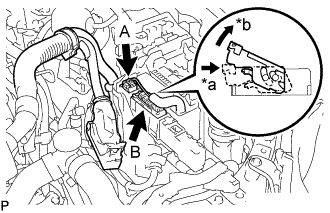
REMOVE ENGINE MOTOR CABLE CLAMP BRACKET (for LHD)
-
Detach the generator cable and motor cable from the engine motor cable clamp bracket.
-
Remove the bolt and engine motor cable clamp bracket.
-
-
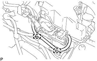
DISCONNECT GENERATOR CABLE
CAUTION:
Wear insulated gloves.
-
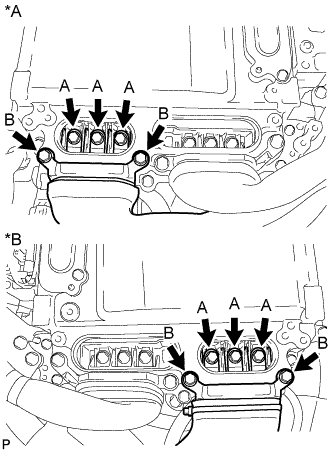
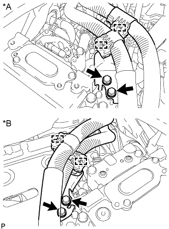
Text in Illustration *A for LHD *B for RHD Using an insulated tool, remove the 3 bolts labeled A in the illustration.
Note
-
Do not damage the terminals, connector housings or inverter with converter assembly when disconnecting them.
-
Do not touch the connector waterproofing rubber or terminals.
-
Do not allow any foreign objects or water to enter the inverter with converter assembly.
-
-
Using an insulated tool, remove the 2 bolts labeled B in the illustration.
Note
-
Do not damage the terminals, connector housings or inverter with converter assembly when disconnecting them.
-
Do not touch the connector waterproofing rubber or terminals.
-
Insulate the removed terminals with insulating tape.
-
Do not allow any foreign objects or water to enter the inverter with converter assembly.
-
-
-
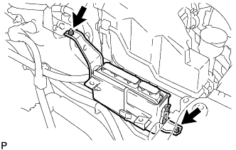
DISCONNECT MOTOR CABLE
CAUTION:
Wear insulated gloves.
-
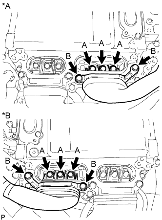
Text in Illustration *A for LHD *B for RHD Using an insulated tool, remove the 3 bolts labeled A in the illustration.
Note
-
Do not damage the terminals, connector housings or inverter with converter assembly when disconnecting them.
-
Do not touch the connector waterproofing rubber or terminals.
-
Do not allow any foreign objects or water to enter the inverter with converter assembly.
-
-
Using an insulated tool, remove the 2 bolts labeled B in the illustration.
Note
-
Do not damage the terminals, connector housings or inverter with converter assembly when disconnecting them.
-
Do not touch the connector waterproofing rubber or terminals.
-
Insulate the removed terminals with insulating tape.
-
Do not allow any foreign objects or water to enter the inverter with converter assembly.
-
-
-
DISCONNECT NO. 2 FUEL VAPOR FEED HOSE
-
Slide the clip and disconnect the No. 2 fuel vapor feed hose from the purge VSV.
-
-
REMOVE FUEL TUBE SUB-ASSEMBLY
-
Disconnect the No. 1 fuel tube clamp from the wire harness clamp bracket.
-
Disconnect the fuel tube sub-assembly from the fuel pump with seal sub-assembly Click here.
-
Disconnect the fuel tube sub-assembly from the fuel delivery pipe Click here.
-
-
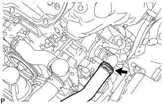
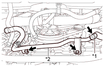
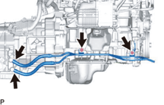
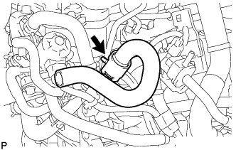
REMOVE RADIATOR HOSE SUB-ASSEMBLY
-
Slide the 2 clamps and remove the radiator hose sub-assembly from the water outlet sub-assembly and radiator assembly.
-
-
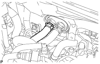
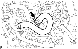
DISCONNECT NO. 2 RADIATOR HOSE SUB-ASSEMBLY
-
Slide the clip and disconnect the No. 2 radiator hose sub-assembly from the water inlet with thermostat sub-assembly.
-
-
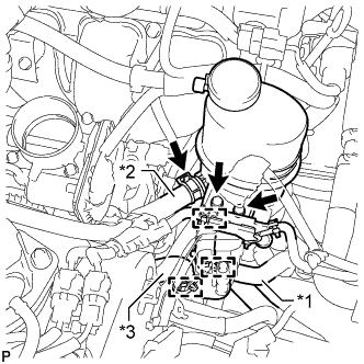
DISCONNECT HEATER WATER HOSE OUTLET A
-
Using pliers, grip the claws of the clip and slide the clip.
-
Disconnect the heater water outlet hose A.
-
-
DISCONNECT HEATER WATER HOSE INLET A
-
Using pliers, grip the claws of the clip and slide the clip.
-
Disconnect the heater water inlet hose A.
-
-
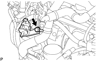
REMOVE HEATER WATER PUMP ASSEMBLY
-
Detach the harness clamp and disconnect the connector.
-
Remove the 2 bolts and disconnect the heater water pump assembly.
-
Using pliers, grip the claws of the clip and slide the 2 clips and disconnect the heater water inlet hose A and heater water inlet hose B and remove the heater water pump assembly.
Note
Do not apply excessive force to the heater water inlet hose.
-
-
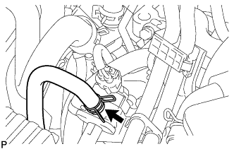
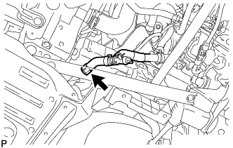
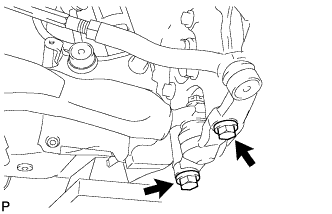
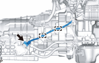
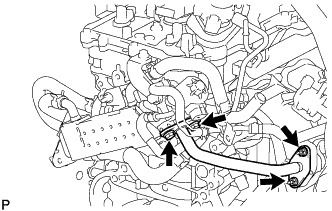
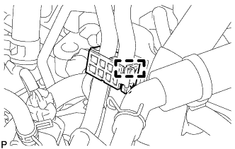
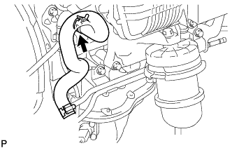
DISCONNECT NO. 2 OIL COOLER OUTLET HOSE
-
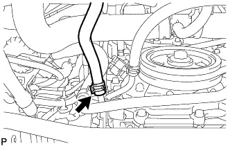
Slide the clip and disconnect the No. 2 oil cooler outlet hose from the oil cooler tube sub-assembly.
-
-
DISCONNECT NO. 2 OIL COOLER INLET HOSE
-
Slide the clip and disconnect the No. 2 oil cooler inlet hose from the oil cooler tube sub-assembly.
-
-
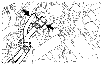
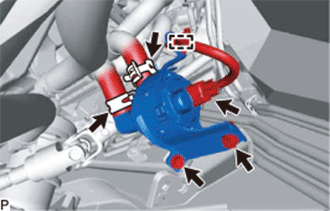
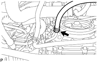
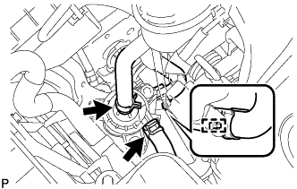
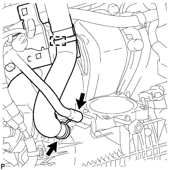
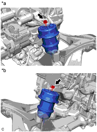
DISCONNECT SUCTION HOSE
-
Remove the bolt and disconnect the suction hose from the compressor with motor assembly.
-
Remove the O-ring from the suction hose.
Note
Seal the openings of the disconnected parts using vinyl tape to prevent moisture and foreign matter from entering them.
-
-
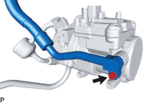
DISCONNECT NO. 1 COOLER REFRIGERANT DISCHARGE HOSE
-
Remove the bolt and disconnect the No. 1 cooler refrigerant discharge hose from the compressor with motor assembly.
-
Remove the O-ring from the No. 1 cooler refrigerant discharge hose.
Note
Seal the openings of the disconnected parts using vinyl tape to prevent moisture and foreign matter from entering them.
-
-
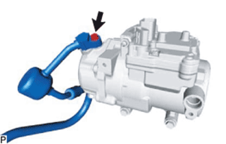
DISCONNECT AIR CONDITIONING HARNESS
-
Text in Illustration *a Green-colored Lock Using a screwdriver, slide the green-colored lock of the connector as shown in the illustration to release it and disconnect the connector.
CAUTION:
Make sure to wear insulated gloves.
Note
Insulate the removed terminals and connector with insulating tape.
-
Detach the 2 wire harness clamps.
-
-
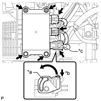
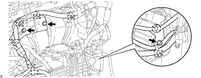
REMOVE ECM
-
Disconnect the wire harness clamp.
-
Push the locks on the 2 levers, raise the 2 levers, and disconnect the 2 ECM connectors.
Note
After disconnecting the ECM connectors, make sure that dirt, water or other foreign matter does not contact the connecting parts of the ECM connectors.
-
Disconnect the 2 wire harness clamps.
-
Remove the 2 nuts and ECM.
Note
If the ECM has been struck or dropped, replace it.
-
-
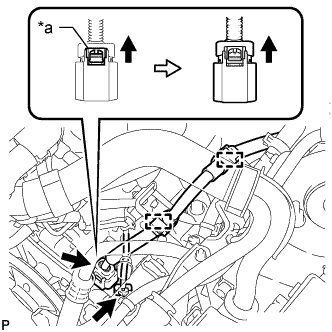
DISCONNECT ENGINE WIRE
Tech Tips
After disconnecting the wire harness, secure it with tape or equivalent to keep it out of the way.
-
Remove the No. 1 engine room relay block cover from the engine room relay block and junction block assembly.
-
Text in Illustration *a Push *b Pull up Disconnect the connector (A) from the No. 2 connector holder.
-
Push in the lock lever of the connector (B) to unlock it and pull up the lock lever.
-
Disconnect the connector (B) from the No. 2 connector holder.
-
Detach the 3 claws and disconnect the No. 2 connector holder from the engine room relay block and junction block assembly.
-
for LHD:
-
Disconnect the 2 wire harness connectors.
-
Detach the wire harness clamp.
-
-
-
REMOVE HV WATER PUMP BRACKET SUB-ASSEMBLY
-
Detach the inverter cooling hose clamp from the inverter water pump with motor assembly.
-
Slide the 2 clamps and disconnect the hybrid water pump inlet hose and No. 1 hybrid water pump outlet hose from the inverter water pump with motor assembly.
Note
Apply insulating tape to the pipe and in the disconnected hose or cover the pipe and hose with plastic bags to prevent entry of foreign matter.
-
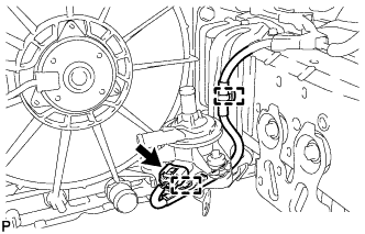
Detach the 2 clamps and disconnect the inverter water pump connector.
Note
Wipe off any coolant from the connectors of the wire harness and inverter water pump with motor, and apply insulating tape to protect them from coolant.
-
Remove the 2 bolts and HV water pump bracket sub-assembly.
-
-
REMOVE NO. 1 HV WATER PUMP OUTLET PIPE
-
Text in Illustration *1 for LHD: No. 2 Inverter Cooling Hose
for RHD: No. 5 Inverter Cooling Hose
*2 No. 1 HV Water Pump Outlet Pipe for LHD:
-
Slide the clip and disconnect the No. 2 inverter cooling hose from the No. 1 HV water pump outlet pipe.
Note
Put pieces of cloth into the pipe and disconnected hose or cover the pipe and disconnected hose with plastic bags to prevent entry of foreign matter.
-
-
for RHD:
-
Slide the clip and disconnect the No. 5 inverter cooling hose from the No. 1 HV water pump outlet pipe.
Note
Put pieces of cloth into the pipe and disconnected hose or cover the pipe and disconnected hose with plastic bags to prevent entry of foreign matter.
-
-
Remove the 2 bolts and No. 1 HV water pump outlet pipe from the stiffening crankcase assembly.
-
-
REMOVE INVERTER RESERVE TANK ASSEMBLY (for LHD)
-
Text in Illustration *1 Hybrid Water Pump Inlet Hose *2 No. 1 Inverter Cooling Hose *3 No. 3 Inverter Cooling Hose Detach the clamp to disconnect the hybrid water pump inlet hose from the No. 1 inverter reserve tank bracket.
Note
Do not remove the clamp from the hybrid water pump inlet hose.
-
Detach the clamp to disconnect the No. 3 inverter cooling hose from the No. 1 inverter reserve tank bracket.
Note
Do not remove the clamp from the No. 3 inverter cooling hose.
-
Detach the wire harness clamp from the inverter reserve tank assembly.
-
Slide the clip and disconnect the No. 1 inverter cooling hose from the inverter reserve tank assembly.
Note
Put pieces of cloth into the pipe and disconnected hose or cover the pipe and disconnected hose with plastic bags to prevent entry of foreign matter.
-
Remove the 2 bolts and inverter reserve tank assembly from the No. 1 inverter reserve tank bracket.
-
-
REMOVE INVERTER RESERVE TANK ASSEMBLY (for RHD)
-
Slide the clip and disconnect the inverter drain hose from the HV radiator outlet pipe.
Note
Put pieces of cloth into the pipe and disconnected hose or cover the pipe and disconnected hose with plastic bags to prevent entry of foreign matter.
-
Text in Illustration *1 No. 3 Inverter Cooling Hose *2 Hybrid Water Pump Inlet Hose Detach the 2 clamps to disconnect the No. 3 inverter cooling hose from the No. 1 inverter reserve tank bracket.
Note
Do not remove the clamps from the No. 3 inverter cooling hose.
-
Detach the clamp to disconnect the hybrid water pump inlet hose from the No. 1 inverter reserve tank bracket.
Note
Do not remove the clamp from the hybrid water pump inlet hose.
-
Remove the 2 bolts and inverter reserve tank assembly from the No. 1 inverter reserve tank bracket.
-
-
REMOVE NO. 1 INVERTER RESERVE TANK BRACKET
-
Remove the bolt and disconnect the No. 3 engine wire from the No. 1 inverter reserve tank bracket.
-
Detach the 2 wire harness clamps from the No. 1 inverter reserve tank bracket.
-
Remove the 2 bolts and No. 1 inverter reserve tank bracket.
-
-
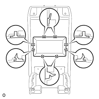
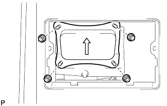
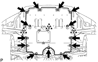
REMOVE NO. 1 REAR FLOOR BOARD SUB-ASSEMBLY
-
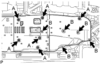
Remove the 5 clips labeled B in the illustration.
-
Loosen the 6 clips labeled A in the illustration and remove the No. 1 rear floor board sub-assembly.
-
-
REMOVE NO. 2 REAR FLOOR BOARD SUB-ASSEMBLY
-
Remove the 5 clips labeled B in the illustration.
-
Loosen the 6 clips labeled A in the illustration and remove the No. 2 rear floor board sub-assembly.
-
-
REMOVE FRONT CENTER FLOOR BRACE
-
Remove the 6 bolts and 2 nuts.
Text in Illustration 
Bolt 
Nut -
Loosen the 2 clips and remove the front center floor brace.
-
-
DISCONNECT HEATED OXYGEN SENSOR
-
Disconnect the heated oxygen sensor connector.
-
Disconnect the clamp.
-
-
REMOVE FRONT EXHAUST PIPE ASSEMBLY
-
Remove the 2 nuts, 6 bolts, 4 compression springs and front exhaust pipe assembly.
-
Remove the 3 gaskets from the front exhaust pipe assembly.
-
-
REMOVE MANIFOLD STAY
-
Remove the 2 bolts and manifold stay.
-
-
REMOVE FRONT CENTER FLOOR BRACE SUB-ASSEMBLY
-
Remove the 4 bolts and front center floor brace sub-assembly.
-
-
REMOVE NO. 1 FUEL TANK PROTECTOR
-
Remove the 4 nuts and No. 1 fuel tank protector.
-
-
REMOVE FRONT NO. 1 FLOOR HEAT INSULATOR
-
Remove the 4 nuts and front No. 1 floor heat insulator.
-
-
REMOVE PROPELLER WITH CENTER BEARING SHAFT ASSEMBLY
-
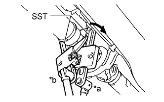
Text in Illustration *a Turn *b Hold Using SST, loosen the adjusting nut until it can be turned by hand.
- SST
- 09922-10010
Note
Make sure to turn SST in the direction shown in the illustration.
Tech Tips
Use 2 of the same type of SST.
-
Text in Illustration *a Matchmark Put matchmarks on the transmission companion flange and flexible coupling.
-
Remove the 3 bolts, 3 washers and 3 nuts.
Note
The propeller intermediate shaft and flexible coupling should not be disconnected.
-
Text in Illustration *a Matchmark Put matchmarks on the differential companion flange and flexible coupling.
-
Remove the 3 bolts, 3 washers and 3 nuts.
Note
The propeller shaft assembly and flexible coupling should not be disconnected.
-
for 2GR-FXE:
Remove the 2 center support bearing dampers and 2 washers.
Tech Tips
Some vehicles are not equipped with the washers.
-
for 2AR-FSE:
Remove the 2 bolts and 2 washers.
Tech Tips
Some vehicles are not equipped with the washers.
-
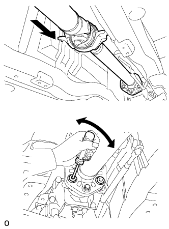
Push the propeller shaft assembly straight forward to compress the propeller shaft assembly and pull out the propeller shaft assembly from the centering pin of the differential.
Note
Press the propeller shaft assembly straight ahead to keep the transmission and propeller intermediate shaft aligned straight.
Tech Tips
If it is difficult to disconnect the flange from the flexible coupling, pry it using a screwdriver.
-
Pull the propeller shaft outward from the vehicle's rear.
Note
The propeller intermediate shaft and propeller shaft assembly should not be disconnected.
-
-
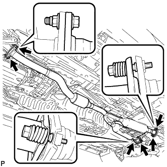
DISCONNECT STEERING SLIDING WITH SHAFT YOKE SUB-ASSEMBLY
-
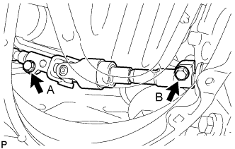
Loosen the bolt labeled A, remove the bolt labeled B.
Note
Do not remove the bolt labeled A, only loosen it.
-
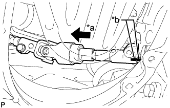
Text in Illustration *a Slide *b Matchmarks Slide the steering sliding with shaft yoke in the direction of the arrow and place matchmarks.
-
Disconnect the steering sliding with shaft yoke from the steering link.
-
-
DISCONNECT FRONT SHOCK ABSORBER ASSEMBLY LH
-
Remove the bolt and nut, and disconnect the lower part of the front shock absorber assembly LH from the front lower suspension arm assembly.
Note
When removing the bolt, keep the nut from rotating.
-
-
DISCONNECT FRONT SHOCK ABSORBER ASSEMBLY RH
Tech Tips
Use the same procedure described for the LH side.
-
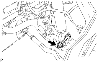
DISCONNECT FRONT LOWER BALL JOINT ASSEMBLY LH
-
Remove the 2 bolts and steering knuckle from the lower ball joint.
-
-
DISCONNECT FRONT LOWER BALL JOINT ASSEMBLY RH
Tech Tips
Use the same procedure described for the LH side.
-
DISCONNECT POWER STEERING LINK WIRE HARNESS
-
Disconnect the 2 wire harness clamps from the bracket.
-
Disconnect the 2 connectors (A and B) from the power steering link assembly.
-
Release the lock of connector (C) and disconnect the connector from the power steering link assembly.
Tech Tips
For the connector with lock lever, pull up the lock lever to disengage the lock.
-
-
DISCONNECT FLOOR SHIFT GEAR SHIFTING ROD SUB-ASSEMBLY
-
Remove the nut and disconnect the floor shift gear shifting rod sub-assembly.
-
-
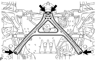
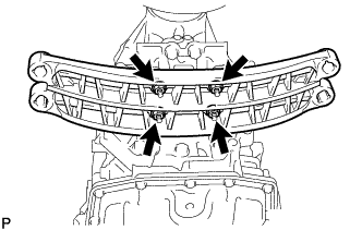
REMOVE FRONT NO. 2 UPPER SUSPENSION MEMBER
-
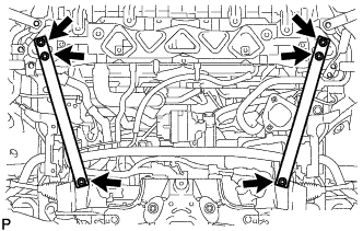
Remove the 6 bolts and 2 front No. 2 upper suspension members.
-
-
REMOVE FRONT LOWER SUSPENSION MEMBER PROTECTOR
-
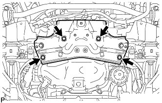
Remove the 4 bolts and front lower suspension member protector from the front suspension crossmember sub-assembly.
-
-
REMOVE ENGINE ASSEMBLY WITH TRANSMISSION
-
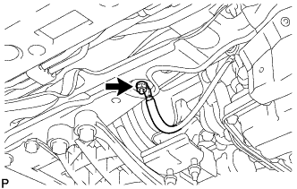
Remove the nut and disconnect the No. 2 earth wire.
-
Text in Illustration *a Attachment Installation Position Place height adjustment attachments and plate lift attachments in the positions shown in the illustration and set an engine lifter underneath the engine assembly with transmission.
Note
-
Using height adjustment attachments and plate lift attachments, place the engine assembly with transmission horizontally.
-
Securely support the engine assembly to prevent it from turning upside down until it is secured to an engine stand.
-
Do not perform any procedures while the engine assembly is suspended because doing so may cause the engine assembly to drop, resulting in injury. However, the engine assembly needs to be suspended when it is installed or removed from an engine stand.
-
To prevent the oil pan from deforming, do not place any attachments under the oil pan of the engine assembly with transmission.
-
-
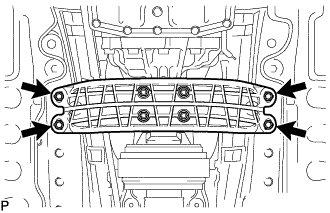
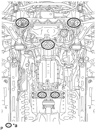
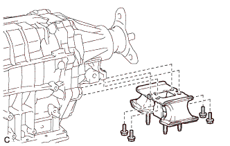
Remove the 4 bolts and separate the rear engine mounting member.
-
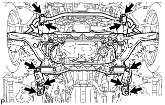
Remove the 4 bolts and separate the front No. 2 stabilizer bracket LH and front No. 2 stabilizer bracket RH.
Text in Illustration Bolt Nut -
Remove the 6 bolts, 2 nuts, strut bar bracket reinforcement LH, strut bar bracket reinforcement RH and front suspension crossmember sub-assembly.
-
Operate the engine lifter to remove the engine assembly with transmission from the vehicle.
Note
-
Make sure that the engine assembly with transmission is clear of all wiring, hoses and the steering sliding with shaft yoke sub-assembly.
-
After removing the engine assembly with transmission, hang the steering sliding with shaft yoke sub-assembly.
-
-
-
INSTALL ENGINE HANGER
-
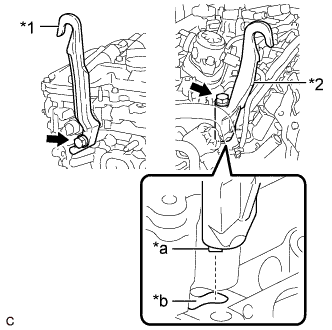
Text in Illustration *1 No. 1 Engine Hanger *2 No. 2 Engine Hanger *a Claw *b Groove Install the No. 1 engine hanger with the bolt.
- Torque:
- 43 N*m { 438 kgf*cm, 32 ft.*lbf }
HINT No. 1 engine hanger 12281-36060 No. 2 engine hanger 12282-36061 Bolt (No. 1 engine hanger) 91552-81040 Bolt (No. 2 engine hanger) 90119-12285 -
Align the claw of the No. 2 engine hanger with the groove of the cylinder head sub-assembly and install the No. 2 engine hanger with the bolt.
- Torque:
- 43 N*m { 438 kgf*cm, 32 ft.*lbf }
Note
When installing the No. 2 engine hanger, make sure the No. 2 engine hanger is securely installed to the cylinder head sub-assembly with the bolt.
-
Using an engine sling device and engine lifter, secure the engine assembly.
Note
-
Adjust the angle of the sling device carefully to prevent the engine assembly or engine hanger from deforming or becoming damaged.
-
Do not perform any procedures while the engine assembly is suspended because doing so may cause the engine assembly to drop, resulting in injury. However, the engine assembly needs to be suspended when it is installed or removed from an engine stand.
-
-
-
REMOVE ENGINE OIL LEVEL DIPSTICK
-
Remove the engine oil level dipstick from the engine oil level dipstick guide.
-
-
REMOVE ENGINE OIL LEVEL DIPSTICK GUIDE
-
Remove the bolt and engine oil level dipstick guide.
-
Remove the O-ring from the engine oil level dipstick guide.
-
-
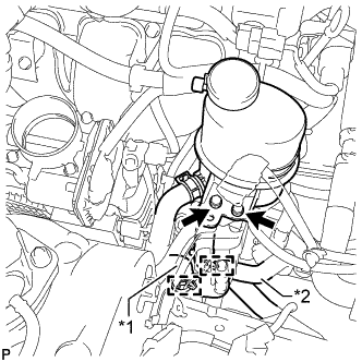
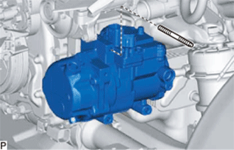
REMOVE COMPRESSOR WITH MOTOR ASSEMBLY
-
Disconnect the motor control connector.
-
Text in Illustration *1 Connector Lock Disconnect the motor drive connector.
-
Using a screwdriver, pull out the connector lock shown in the illustration.
-
Push the release button and disconnect the connector.
CAUTION:
Make sure to wear insulating gloves.
Note
Insulate the removed terminals and connector with insulating tape.
-
-
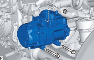
Remove the 2 bolts and nut.
-
Using an E8 ''TORX'' socket wrench, remove the stud bolt and compressor with motor assembly.
-
-
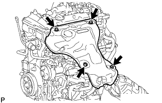
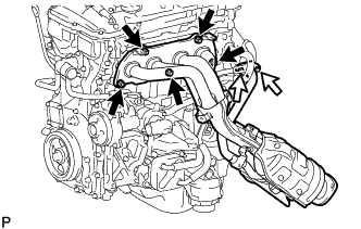
REMOVE NO. 3 EXHAUST MANIFOLD HEAT INSULATOR
-
Remove the 2 nuts and No. 3 exhaust manifold heat insulator from the camshaft housing sub-assembly.
-
-
REMOVE NO. 1 EXHAUST MANIFOLD HEAT INSULATOR
-
Remove the 4 bolts and No. 1 exhaust manifold heat insulator from the exhaust manifold converter sub-assembly.
-
-
REMOVE EXHAUST MANIFOLD CONVERTER SUB-ASSEMBLY
-
w/o EGR System:
-
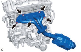
Remove the 5 nuts and exhaust manifold converter sub-assembly.
-
Remove the gasket from the cylinder head sub-assembly.
-
-
w/ EGR System:
-
Remove the 2 bolts, 5 nuts and exhaust manifold converter sub-assembly.
Text in Illustration Nut Bolt -
Remove the gasket and EGR cooler gasket from the cylinder head sub-assembly and EGR cooler assembly.
-
-
-
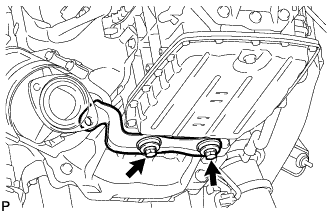
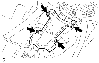
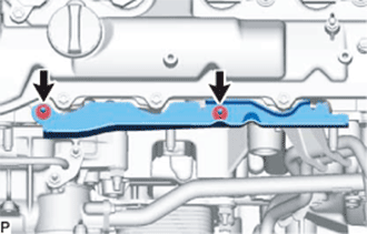
REMOVE MOTOR HEAT INSULATOR
-
Remove the 4 bolts and motor heat insulator from the hybrid vehicle transmission assembly.
-
-
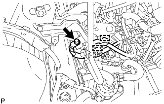
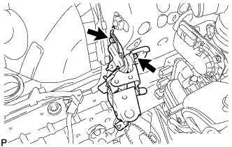
DISCONNECT WIRE HARNESS
-
Text in Illustration *a Generator Resolver Sensor Connector *b Motor Resolver Sensor Connector Disconnect the generator resolver sensor connector.
-
Disconnect the motor resolver sensor connector.
-
Disconnect the 2 clamps and wire harness from the hybrid vehicle transmission assembly.
-
Remove the 3 bolts and disconnect the wire harness from the hybrid vehicle transmission assembly.
-
Disconnect the shift lever position sensor connector.
-
Disconnect the 2 clamps and wire harness from the hybrid vehicle transmission assembly.
-
-
REMOVE OIL COOLER WITHOUT HOSE TUBE SUB-ASSEMBLY
-
Slide the 2 clips and disconnect the oil cooler without hose tube sub-assembly from the hybrid vehicle transmission assembly.
-
Remove the 2 bolts and oil cooler without hose tube sub-assembly from the engine assembly.
-
-
SUPPORT HYBRID VEHICLE TRANSMISSION ASSEMBLY
-
Support the hybrid vehicle transmission assembly with a transmission jack.
Note
-
Using an engine sling device and engine lift, secure the engine assembly before service.
-
To prevent the transmission oil pan sub-assembly from deforming, do not place any attachments under the transmission oil pan sub-assembly of the hybrid vehicle transmission assembly.
-
To protect the transmission oil pan sub-assembly, do not use the transmission oil pan sub-assembly and transmission oil pan sub-assembly setting bolt to support the hybrid vehicle transmission assembly. Place attachments on the transmission jack saddle.
-
Make sure that the attachments and the transmission oil pan sub-assembly are centered on the transmission jack.
-
Secure the hybrid vehicle transmission assembly to the transmission jack using a suitable adapter, such as a rope or attachment.
-
-
-
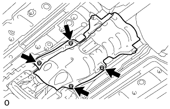
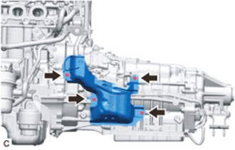
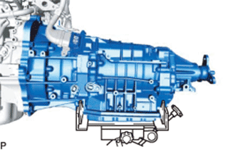
REMOVE HYBRID VEHICLE TRANSMISSION ASSEMBLY
-
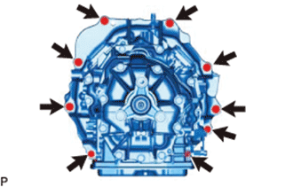
Remove the 9 bolts and hybrid vehicle transmission assembly from the engine assembly.
Note
To avoid damage to the 2 knock pins, do not pry between the hybrid vehicle transmission assembly and the engine assembly.
-
-
REMOVE ENGINE WIRE
-
Remove the engine wire from the engine assembly.
-
-
REMOVE TRANSMISSION INPUT DAMPER ASSEMBLY
-
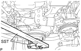
Using SST, hold the crankshaft pulley assembly.
- SST
- 09213-54015
- 09330-00021
Tech Tips
SST (Crankshaft pulley holding tool) fixing bolt part No.: 91551-80650 (2 pcs)
-
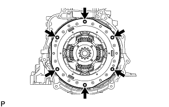
Remove the 6 bolts and transmission input damper assembly.
-
-
REMOVE FLYWHEEL SUB-ASSEMBLY
-
Using SST, hold the crankshaft pulley assembly.
- SST
- 09213-54015
- 09330-00021
Tech Tips
SST (Crankshaft pulley holding tool) fixing bolt part No.: 91551-80650 (2 pcs)
-
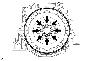
Remove the 8 bolts and flywheel sub-assembly.
-
-
REMOVE FAN AND GENERATOR V BELT
-
Prepare a clean durable piece of cloth and fold it several times.
Tech Tips
Fold the cloth several times to make it thicker.
-
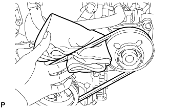
Pass the cloth under the fan and generator V belt between the crankshaft pulley assembly and engine water pump assembly as shown in the illustration.
Note
Position the cloth so that the part closest to the engine is longer.
-
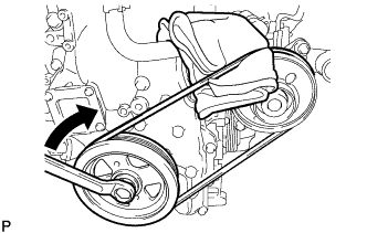
Slightly rotate the crankshaft pulley assembly clockwise so that the cloth is pulled between the fan and generator V belt and engine water pump assembly.
Note
Do not allow the cloth to be pulled further than the top center of the engine water pump assembly.
-
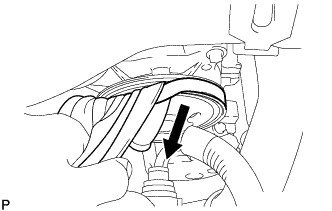
Fold the cloth over the fan and generator V belt and pull it as shown in the illustration while gradually rotating the crankshaft pulley assembly clockwise.
Note
Pull the cloth until the upper part of the fan and generator V belt comes off the engine water pump assembly.
-
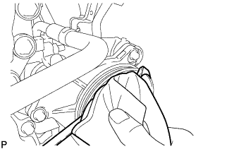
Check that the upper part of the fan and generator V belt is off the engine water pump assembly, then rotate the crankshaft pulley assembly clockwise to remove the fan and generator V belt.
-
-
REMOVE THROTTLE BODY WITH MOTOR ASSEMBLY
-
Disconnect the throttle body with motor assembly connector.
-
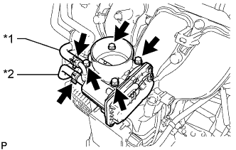
Text in Illustration *1 No. 3 Water By-pass Hose *2 No. 2 Water By-pass Hose Slide the 2 clamps and disconnect the No. 3 water by-pass hose and No. 2 water by-pass hose from the throttle body with motor assembly.
-
Remove the 4 bolts and throttle body with motor assembly from the intake manifold.
-
Remove the throttle body gasket from the intake manifold.
-
-
REMOVE INJECTOR DRIVER
-
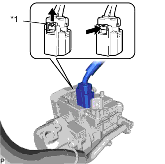
Text in Illustration *a Lock Lever *b Lock *c Connector (with Lock) Push the lock and move each lock lever in the direction indicated by the arrow to disconnect the connector (with lock) from the injector driver.
-
Disconnect the 2 injector driver connectors.
-
Remove the 2 bolts, 2 nuts and injector driver from the intake manifold.
Note
Be careful not to drop or strike the injector driver.
-
-
REMOVE PURGE VSV
-
Disconnect the purge VSV connector.
-
Disconnect the No. 2 fuel vapor feed hose from the purge VSV.
-
Slide the clip and disconnect the No. 2 fuel vapor feed hose from the purge VSV.
-
Remove the bolt and purge VSV from the wire harness clamp bracket.
-
-
REMOVE NO. 2 EGR PIPE (w/ EGR System)
-
Remove the 2 bolts, 2 nuts, No. 2 EGR pipe, No. 2 EGR pipe gasket and EGR inlet gasket from the EGR valve assembly and intake manifold.
-
-
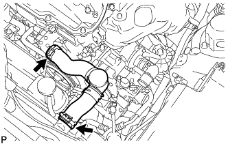
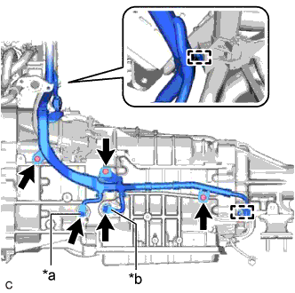
REMOVE INTAKE MANIFOLD
-
Detach the clamp to disconnect the fuel tube from the wire harness clamp bracket.
-
Disconnect the No. 2 fuel vapor feed hose from the intake manifold.
-
Slide the clip and disconnect the ventilation hose from the intake manifold.
-
Detach the clamp to disconnect the ventilation hose from the wire harness clamp bracket.
-
Detach the 7 wire harness clamps to disconnect the wire harness from the 2 wire harness clamp brackets and intake manifold.
-
Detach the clamp to disconnect the No. 2 water by-pass hose from the intake manifold.
-
Remove the 3 bolts and 2 wire harness clamp brackets from the intake manifold.
-
Remove the 7 bolts, intake manifold stay and intake manifold.
-
Remove the gasket from the intake manifold.
-
-
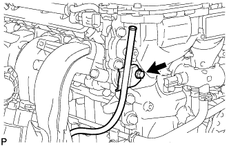
REMOVE HEATER WATER HOSE OUTLET A
-
Remove the water hose set from the heater water hose outlet A.
-
Slide the clip and disconnect the heater water hose outlet A from the No. 2 water by-pass pipe.
-
-
REMOVE HEATER WATER HOSE INLET B
-
Slide the clip and disconnect the heater water hose inlet B from the No. 3 water by-pass pipe.
-
-
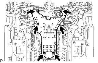
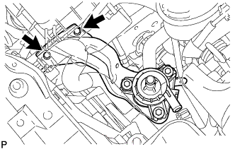
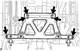
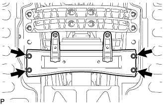
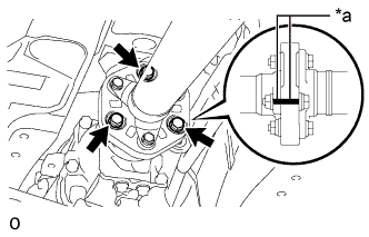
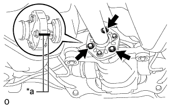
REMOVE FRONT SUSPENSION CROSSMEMBER SUB-ASSEMBLY
-
Text in Illustration *a LH Side *b RH Side Remove the 2 bolts and front suspension crossmember sub-assembly from the engine assembly.
-
-
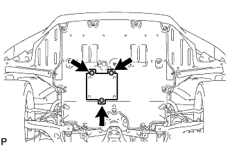
REMOVE FRONT ENGINE MOUNTING INSULATOR
Tech Tips
Perform this procedure only when replacement of the front engine mounting insulator is necessary.
-
Remove the 2 nuts and 2 front engine mounting insulators from the front suspension crossmember sub-assembly.
Text in Illustration *a LH Side *b RH Side
-
-
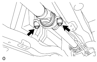
REMOVE REAR ENGINE MOUNTING MEMBER
Tech Tips
Perform this procedure only when replacement of the rear No. 1 engine mounting insulator is necessary.
-
Remove the 4 nuts and rear engine mounting member from the rear No. 1 engine mounting insulator.
-
-
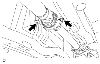
REMOVE REAR NO. 1 ENGINE MOUNTING INSULATOR
Tech Tips
Perform this procedure only when replacement of the rear No. 1 engine mounting insulator is necessary.
-
Remove the 4 bolts and rear No. 1 engine mounting insulator from the hybrid vehicle transmission assembly.
-
-
INSTALL ENGINE ASSEMBLY TO ENGINE STAND
-
Install the engine assembly to an engine stand.
Note
-
Adjust the angle of the sling device carefully to prevent the engine assembly or engine hanger from deforming or becoming damaged.
-
Do not perform any procedures while the engine assembly is suspended because doing so may cause the engine assembly to drop, resulting in injury. However, the engine assembly needs to be suspended when it is installed or removed from an engine stand.
-
-
Remove the 2 bolts, No. 1 engine hanger and No. 2 engine hanger.
-
-
INSPECT EXHAUST MANIFOLD CONVERTER SUB-ASSEMBLY
-
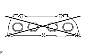
Using a precision straightedge and feeler gauge, check the surface which contacts the cylinder head sub-assembly for warpage.
Maximum warpage 0.7 mm (0.0276 in.) If the warpage is more than the maximum, replace the exhaust manifold converter sub-assembly.
-