INVERTER WITH CONVERTER REMOVAL

-
PRECAUTION
CAUTION:
Be sure to read Precaution thoroughly before servicing Click here.
Note
After turning the power switch off, waiting time may be required before disconnecting the cable from the battery terminal. Therefore, make sure to read the disconnecting the cable from the battery terminal notice before proceeding with work Click here.
-
REMOVE LUGGAGE COMPARTMENT FLOOR MAT
-
Remove the luggage compartment floor mat.
-
-
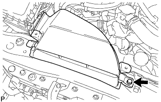
REMOVE LUGGAGE COMPARTMENT TRIM COVER LH
-
Remove the luggage compartment trim cover LH.
-
-
DISCONNECT CABLE FROM AUXILIARY BATTERY NEGATIVE TERMINAL
Note
When disconnecting the cable, some systems need to be initialized after the cable is reconnected Click here.
-
Disconnect the cable from the auxiliary battery negative (-) terminal.
Tech Tips
Both cables should be disconnected to prevent the AMD terminal from shorting to ground.
-
Remove the terminal cover.
-
Remove the nut and disconnect the cable from the auxiliary battery positive (+) terminal.
Tech Tips
Both cables should be disconnected to prevent the AMD terminal from shorting to ground.
-
-
REMOVE SERVICE PLUG GRIP
-
REMOVE ENGINE ROOM SIDE COVER
-
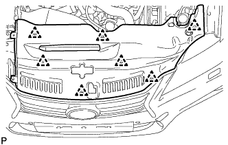
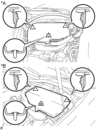
Remove the 4 clips and engine room side cover.
-
-
REMOVE COOL AIR INTAKE DUCT SEAL
-
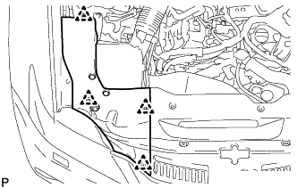
Remove the 7 clips and cool air intake duct seal.
-
-
REMOVE NO. 1 AIR CLEANER INLET
-
Remove the bolt and No. 1 air cleaner inlet.
-
-
REMOVE ENGINE UNDER COVER
-
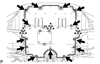
Remove the 13 screws, 3 clips and engine under cover.
-
-
REMOVE FRONT SUSPENSION MEMBER BRACE
-
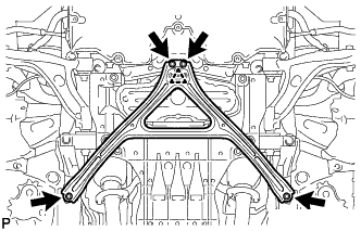
Remove the 4 bolts, and then turn the clip and remove the front suspension member brace.
Tech Tips
Do not remove the clip from the front suspension member brace.
-
-
REMOVE NO. 2 ENGINE UNDER COVER
-
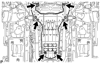
Remove the 4 screws, 2 grommets and No. 2 engine under cover.
-
-
DRAIN COOLANT (for Inverter)
Note
-
Do not reuse the drained coolant because it may contain foreign objects.
-
Collect the drained coolant and measure its volume to establish a benchmark. When adding coolant, make sure to add more coolant than the measured amount.
-
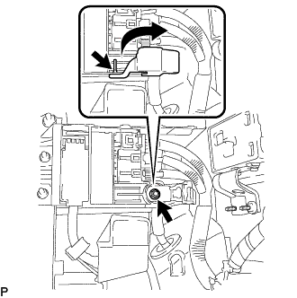
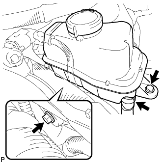
Remove the reservoir tank cap.
CAUTION:
To avoid the danger of being burned, do not remove the reservoir tank cap while the coolant for the inverter is still hot.
-
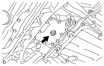
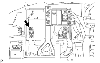
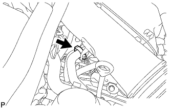
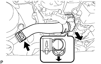
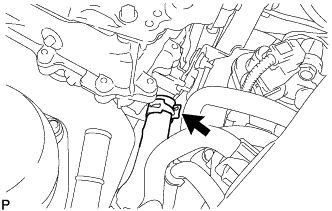
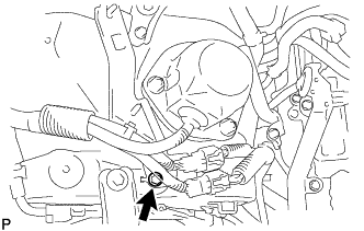
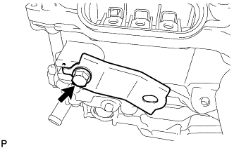
Using a 10 mm hexagon wrench, remove the drain plug indicated in the illustration and drain the coolant.
CAUTION:
Use caution when handling coolant immediately after driving or in summer because it may be hot.
-
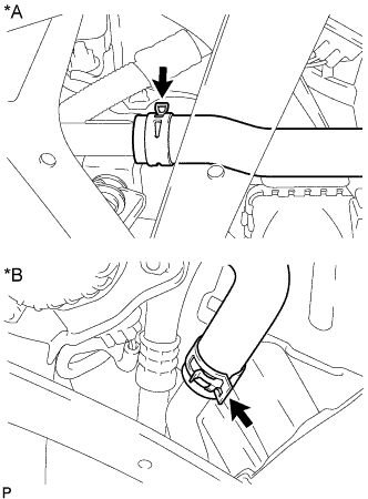
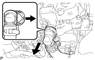
Text in Illustration *A for LHD *B for RHD Disconnect the No. 5 inverter cooling hose.
-
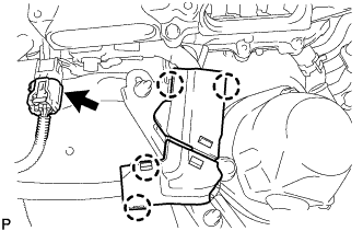
Install the plug with a new gasket.
- Torque:
- 39 N*m { 398 kgf*cm, 29 ft.*lbf }
-
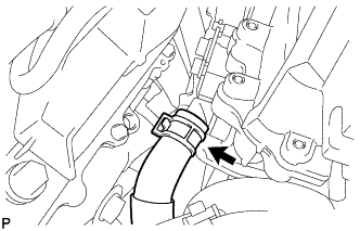
Connect the No. 5 inverter cooling hose.
-
-
REMOVE V-BANK COVER SUB-ASSEMBLY
-
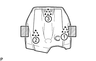
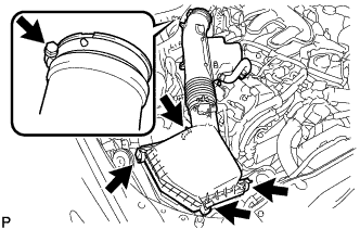
Place both hands on the sides of the cover as shown in the illustration, lift the cover to detach the 2 clips near the front in the order shown in the illustration, and then lift the cover further to detach the rear clip and remove the cover.
Text in Illustration 
Areas to place hands when lifting cover Note
If the cover is lifted rearward or forward and to the right or left at the same time, the cover may be damaged.
-
-
REMOVE AIR CLEANER CAP WITH AIR CLEANER HOSE (for LHD)
-
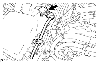
Disconnect the mass air flow meter connector.
-
Disconnect the clamp from the air cleaner.
-
Disconnect the VSV hose.
-
Disconnect the 4 clamps.
-
Remove the hose clamp and air cleaner cap with air cleaner hose.
-
-
REMOVE INVERTER COVER
-
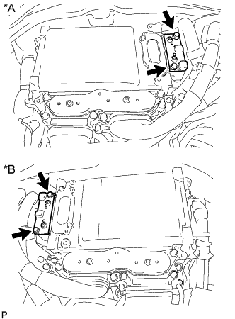
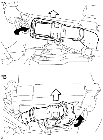
Text in Illustration *A for LHD *B for RHD Raise the front of the inverter cover to detach the clip. Then remove the 2 inverter cover clips from the bracket, and remove the inverter cover.
-
-
REMOVE CONNECTOR COVER ASSEMBLY
CAUTION:
-
Do not touch the high voltage connectors and terminals for 10 minutes after the service plug grip is removed.
-
Wear insulated gloves.
Note
Do not start the hybrid system with the service plug grip removed because it may cause a malfunction.
-
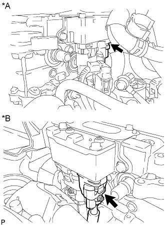
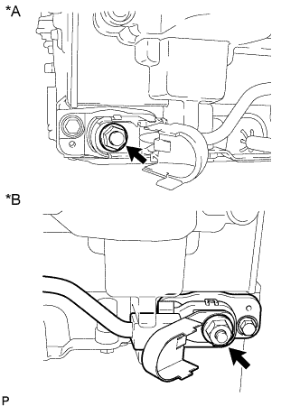
Text in Illustration *A for LHD *B for RHD Using an insulated tool, remove the 2 bolts and connector cover assembly.
Note
-
Make sure to pull the connector cover assembly straight up, as a connector is connected to the bottom of the cover.
-
Do not allow any foreign objects or water to enter the inverter with converter assembly.
-
-
-
CHECK TERMINAL VOLTAGE
CAUTION:
Wear insulated gloves.
Note
Do not allow any foreign objects or water to enter the inverter with converter assembly.
-
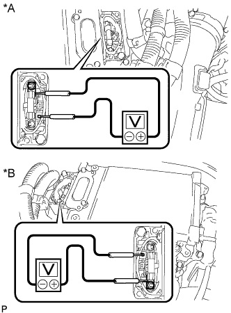
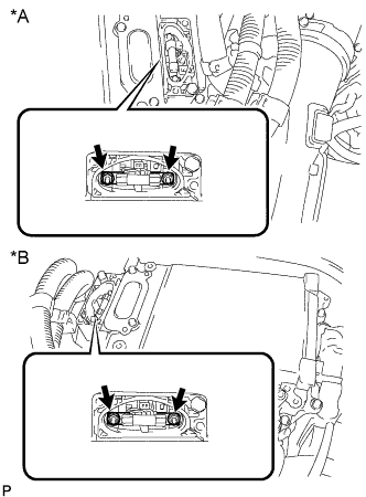
Text in Illustration *A for LHD *B for RHD Using a voltmeter, measure the voltage between the terminals of the 2 phase connectors.
Standard voltage 0 V Tech Tips
Use a measuring range of DC 750 V or more on the voltmeter.
-
-
TEMPORARILY INSTALL CONNECTOR COVER ASSEMBLY
CAUTION:
Wear insulated gloves.
-
Temporarily install the connector cover assembly with the bolt to prevent any foreign objects or water from entering the inverter with converter assembly.
-
-
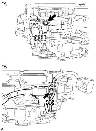
REMOVE INVERTER MOTOR CABLE BRACKET ASSEMBLY
-
Text in Illustration *A for LHD *B for RHD Detach the 2 clamps from the inverter motor cable bracket assembly.
-
Remove the 2 bolts and inverter motor cable bracket assembly.
-
-
REMOVE INVERTER TERMINAL COVER
CAUTION:
Wear insulated gloves.
-
for Type A:
-
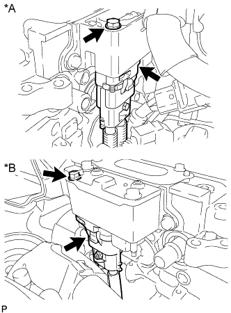
Text in Illustration *A for LHD *B for RHD Using an insulated tool, remove the 2 bolts and inverter terminal cover.
Note
-
Make sure to pull the inverter terminal cover straight up, as a connector is connected to the bottom of the cover.
-
Do not touch the inverter terminal cover waterproofing rubber.
-
-
-
for Type B:
-
Text in Illustration *A for LHD *B for RHD Using an insulated tool, remove the 3 bolts and inverter terminal cover.
Note
-
Make sure to pull the inverter terminal cover straight up, as a connector is connected to the bottom of the cover.
-
Do not touch the inverter terminal cover waterproofing rubber.
-
-
-
-
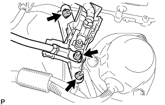
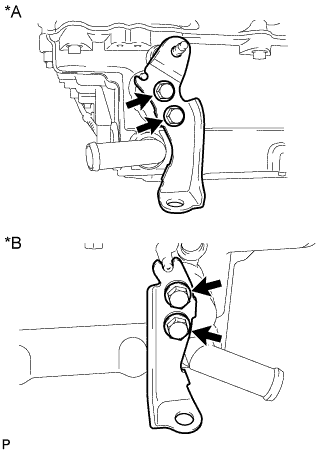
DISCONNECT GENERATOR CABLE
CAUTION:
Wear insulated gloves.
-
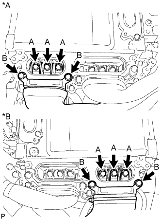
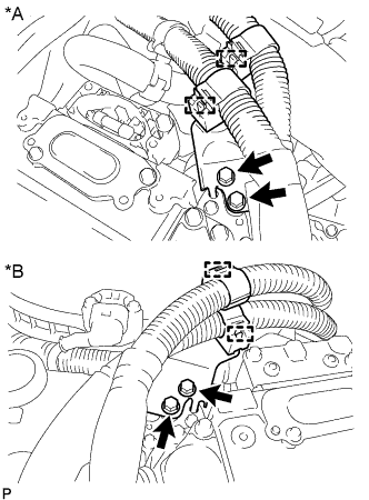
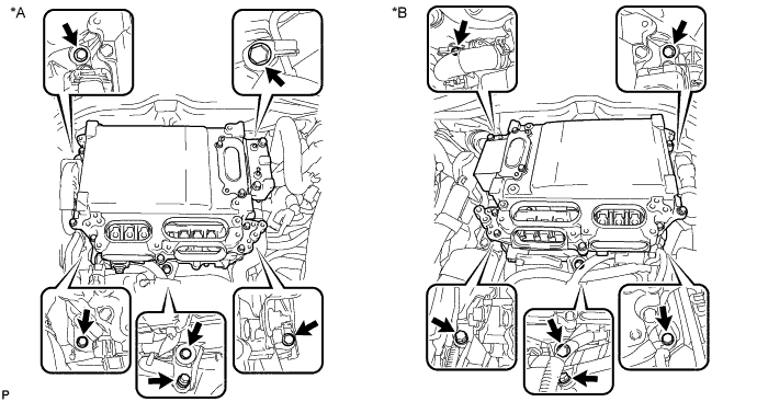
Text in Illustration *A for LHD *B for RHD Using an insulated tool, remove the 3 bolts labeled A in the illustration.
Note
-
Do not damage the terminals, connector housings or inverter with converter assembly when disconnecting them.
-
Do not touch the connector waterproofing rubber or terminals.
-
Do not allow any foreign objects or water to enter the inverter with converter assembly.
-
-
Using an insulated tool, remove the 2 bolts labeled B in the illustration.
Note
-
Do not damage the terminals, connector housings or inverter with converter assembly when disconnecting them.
-
Do not touch the connector waterproofing rubber or terminals.
-
Insulate the removed terminals with insulating tape.
-
Do not allow any foreign objects or water to enter the inverter with converter assembly.
-
-
-
DISCONNECT MOTOR CABLE
CAUTION:
Wear insulated gloves.
-
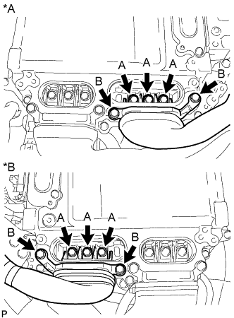
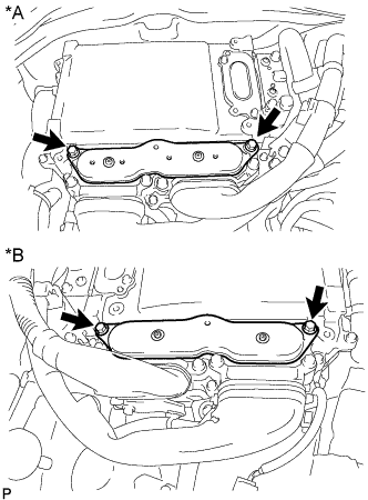
Text in Illustration *A for LHD *B for RHD Using an insulated tool, remove the 3 bolts labeled A in the illustration.
Note
-
Do not damage the terminals, connector housings or inverter with converter assembly when disconnecting them.
-
Do not touch the connector waterproofing rubber or terminals.
-
Do not allow any foreign objects or water to enter the inverter with converter assembly.
-
-
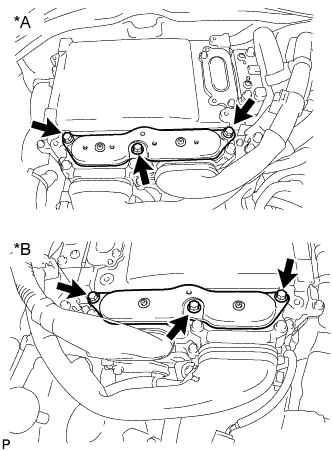
Using an insulated tool, remove the 2 bolts labeled B in the illustration.
Note
-
Do not damage the terminals, connector housings or inverter with converter assembly when disconnecting them.
-
Do not touch the connector waterproofing rubber or terminals.
-
Insulate the removed terminals with insulating tape.
-
Do not allow any foreign objects or water to enter the inverter with converter assembly.
-
-
-
REMOVE NO. 1 INVERTER COOLING OUTLET HOSE (for LHD)
-
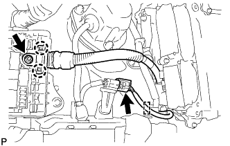
Release the retainer and disconnect the No. 1 inverter cooling outlet hose from the inverter with converter assembly.
-
Slide the clamp and remove the No. 1 inverter cooling outlet hose.
Note
Apply insulating tape to the pipes and in the disconnected hoses, or cover the pipes and hoses with plastic bags to prevent foreign matter from entering the cooling system and to prevent coolant from spilling near the inverter with converter assembly.
-
-
DISCONNECT NO. 1 INVERTER COOLING INLET HOSE (for LHD)
-
Slide the clamp and disconnect the No. 1 inverter cooling inlet hose from the inverter with converter assembly.
Note
Apply insulating tape to the pipes and in the disconnected hoses, or cover the pipes and hoses with plastic bags to prevent foreign matter from entering the cooling system and to prevent coolant from spilling near the inverter with converter assembly.
-
-
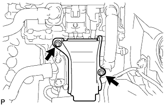
REMOVE INVERTER RESERVOIR TANK ASSEMBLY (for RHD)
-
Remove the 2 bolts and disconnect the inverter reservoir tank assembly from the No. 4 inverter cooling hose.
-
Release the retainer and disconnect the No. 2 inverter cooling outlet hose from the inverter with converter assembly.
Note
Apply insulating tape to the pipes and in the disconnected hoses, or cover the pipes and hoses with plastic bags to prevent foreign matter from entering the cooling system and to prevent coolant from spilling near the inverter with converter assembly.
-
-
DISCONNECT NO. 2 INVERTER COOLING INLET HOSE (for RHD)
-
Slide the clamp and disconnect the No. 2 inverter cooling inlet hose from the inverter with converter assembly.
Note
Apply insulating tape to the pipes and in the disconnected hoses, or cover the pipes and hoses with plastic bags to prevent foreign matter from entering the cooling system and to prevent coolant from spilling near the inverter with converter assembly.
-
-
DISCONNECT INVERTER BUS-BAR PLATE SUB-ASSEMBLY
-
for LHD:
-
Detach the 4 claws and disconnect the connector cover.
-
Disconnect the connector.
-
Remove the 3 nuts and disconnect the wire harness and inverter bus-bar plate sub-assembly.
-
Remove the bolt and disconnect the wire harness bracket.
-
-
for RHD:
-
Remove the relay block cover.
-
Disconnect the connector and detach the clamp.
-
Remove the nut, detach the 2 claws and disconnect the inverter bus-bar plate sub-assembly.
-
-
-
REMOVE WIRE HARNESS CLAMP BRACKET A (for LHD)
-
Remove the 2 nuts and wire harness clamp bracket A.
-
-
REMOVE INVERTER WITH CONVERTER ASSEMBLY
CAUTION:
Wear insulated gloves.
-
Loosen the 6 bolts as shown in the illustration.
Text in Illustration *A for LHD *B for RHD Note
-
Since the inverter with converter is very heavy, 2 people are needed to remove the inverter with converter. When removing the inverter with converter assembly, do not damage the parts around it.
-
To prevent damage, do not hold the inverter with converter assembly by the connectors.
-
To prevent damage due to static electricity, do not touch the terminals of the disconnected connectors.
-
-
Text in Illustration *A for LHD *B for RHD Raise the lock lever and disconnect the connector.
-
Remove the bolt and connector cover assembly.
Note
-
Make sure to pull the connector cover straight up, as a connector is connected to the bottom of the cover.
-
Do not allow any foreign objects or water to enter the inverter with converter assembly.
-
-
Text in Illustration *A for LHD *B for RHD Disconnect the air conditioning harness.
Note
-
Do not damage the terminals, connector housings or inverter with converter assembly when disconnecting them.
-
Do not touch the connector waterproofing rubber or terminals.
-
Insulate the removed terminals with insulating tape.
-
Do not allow any foreign objects or water to enter the inverter with converter assembly.
-
-
Text in Illustration *A for LHD *B for RHD Using an insulated tool, remove the bolt and disconnect the No. 4 floor wire.
Note
-
Do not damage the terminals, connector housings or inverter with converter assembly when disconnecting them.
-
Do not touch the connector waterproofing rubber or terminals.
-
Insulate the removed terminals with insulating tape.
-
Do not allow any foreign objects or water to enter the inverter with converter assembly.
-
-
Temporarily install the connector cover assembly with the bolt to prevent any foreign objects or water from entering the inverter with converter assembly.
-
Remove the 6 bolts, and inverter with converter assembly and No. 6 inverter bracket.
Note
-
Since the inverter with converter assembly is very heavy, 2 people are needed to remove the inverter with converter assembly. When removing the inverter with converter assembly, do not damage the parts around it.
-
Insulate the removed terminals with insulating tape.
-
To prevent damage, do not hold the inverter with converter assembly by the connectors.
-
To prevent damage due to static electricity, do not touch the terminals of the disconnected connectors.
-
-
Even after the coolant is drained, coolant remains in the inverter with converter due to its internal structure. Therefore, seal or cover the pipes when removing the inverter with converter assembly to prevent coolant from spilling out or foreign matter from entering the inverter with converter assembly.
-
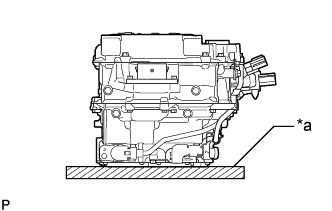
Text in Illustration *a Cushion When removing and storing the inverter with converter assembly, make sure to install the inverter terminal cover assembly and place a cushion under the inverter with converter assembly to protect it.
Note
Do not place the inverter with converter assembly upside-down.
-
-
REMOVE NO. 4 INVERTER BRACKET
-
Text in Illustration *A for LHD *B for RHD Remove the 2 bolts and No. 4 inverter bracket.
-
for RHD:
Remove the bolt and wire harness bracket.
-
-
REMOVE INVERTER BUS-BAR PLATE SUB-ASSEMBLY
-
Text in Illustration *A for LHD *B for RHD Detach the 2 wire harness clamps and remove the bolt.
-
Text in Illustration *A for LHD *B for RHD Open the cover.
Note
Do not twist the cover excessively when opening it.
-
Remove the nut and inverter bus-bar plate sub-assembly.
Note
-
If the stud bolt becomes loose when removing the nut, tighten the stud bolt to a torque of 10N*m (107kgf*cm 7ft.*lbf).
-
If the inverter bus-bar plate sub-assembly is dropped or deformed, replace it with a new one.
-
-
-
REMOVE HIGH VOLTAGE FUSE
CAUTION:
Wear insulated gloves.
Tech Tips
Perform this procedure only when replacement of the high voltage fuse is necessary.
-
Remove the bolt and connector cover assembly.
Note
-
Make sure to pull the connector cover assembly straight up, as a connector is connected to the bottom of the cover.
-
Do not allow any foreign objects or water to enter the inverter with converter assembly.
-
-
Text in Illustration *A for LHD *B for RHD Remove the 2 nuts and high voltage fuse.
-
Temporarily install the connector cover assembly with the bolt to prevent any foreign objects or water from entering the inverter with converter assembly.
-