COOLANT (for Inverter) REPLACEMENT

-
REMOVE ENGINE UNDER COVER
-
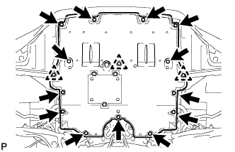
Remove the 13 screws, 3 clips and engine under cover.
-
-
REMOVE FRONT SUSPENSION MEMBER BRACE
-
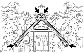
Remove the 4 bolts, and then turn the clip and remove the front suspension member brace.
Tech Tips
Do not remove the clip from the front suspension member brace.
-
-
REMOVE NO. 2 ENGINE UNDER COVER
-
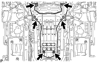
Remove the 4 screws, 2 grommets and No. 2 engine under cover.
-
-
DRAIN COOLANT (for Inverter)
Note
-
Do not reuse the drained coolant because it may contain foreign objects.
-
Collect the drained coolant and measure its volume to establish a benchmark. When adding coolant, make sure to add more coolant than the measured amount.
-
Remove the reservoir tank cap.
CAUTION:
To avoid the danger of being burned, do not remove the reservoir tank cap while the coolant for the inverter is still hot.
-
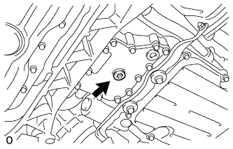
Using a 10 mm hexagon wrench, remove the drain plug indicated in the illustration and drain the coolant.
CAUTION:
Use caution when handling coolant immediately after driving or in summer because it may be hot.
-
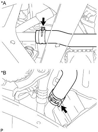
Text in Illustration *A for LHD *B for RHD Disconnect the No. 5 inverter cooling hose.
-
Install the plug with a new gasket.
- Torque:
- 39 N*m { 398 kgf*cm, 29 ft.*lbf }
-
Connect the No. 5 inverter cooling hose.
-
-
ADD COOLANT (for Inverter)
Note
-
Do not reuse the drained coolant because it may contain foreign objects.
-
If the vehicle is driven with air in the inverter cooling system, damage may occur and the following DTCs may be set.
DTC Code Detection Item P0A04-725 Motor Electronics Coolant Temperature Sensor Circuit Intermittent P0A01-726 Motor Electronics Coolant Temperature Sensor Circuit Range / Performance P0A08-264 DC / DC Converter Status Circuit P0A78-284 Drive Motor "A" Inverter Performance P0A78-286 Drive Motor "A" Inverter Performance P0A7A-322 Generator Inverter Performance P0A7A-324 Generator Inverter Performance P0A93-346 Inverter Cooling System Performance P0A94-553 DC / DC Converter Performance P0A94-557 DC / DC Converter Performance P0AF1-276 Drive Motor Inverter Temperature Sensor "A" Circuit Intermittent / Erratic P0AEE-277 Motor Inverter Temperature Sensor "A" Circuit Range / Performance P0BD0-314 Generator Inverter Temperature Sensor Circuit Range / Erratic P0BCD-315 Generator Inverter Temperature Sensor Circuit Range / Performance P0C3C-625 DC / DC Converter Temperature Sensor "A" Intermittent / Erratic P0C39-626 DC / DC Converter Temperature Sensor "A" Range / Performance P0C41-627 DC / DC Converter Temperature Sensor "B" Intermittent / Erratic P0C3E-628 DC / DC Converter Temperature Sensor "B" Range / Performance P0C73-776 Motor Electronics Coolant Pump "A" Control Performance
-
Slowly pour coolant into the reservoir tank until it reaches the FULL line.
Standard Capacity Item Specified Condition for LHD 3.1 liters (3.3 US qts, 2.7 Imp. qts.) for RHD 2.9 liters (3.0 US qts, 2.6 Imp. qts.) Note
To prevent foreign matter such as dust or dirt from entering the cooling system, make sure to confirm that the container used to add coolant is clean and free of foreign matter such as dust or dirt.
-
When using the GTS:
-
Connect the GTS to the DLC3.
-
Turn the power switch on (IG).
-
Enter the following menus: Powertrain / Hybrid Control / Active Test / Activate the Water Pump.
-
Keep the coolant at the FULL line in the reservoir tank to compensate for the drop in coolant level when the air bleeds.
Standard Air bleeding from the inverter cooling system is completed when the noise made by the inverter water pump assembly becomes smaller and the circulation of coolant in the reservoir tank improves. Tech Tips
-
If free spinning of the inverter water pump is detected for approximately 5 seconds, failsafe control will be activated to suspend the operation of the pump for approximately 15 seconds and resume operation for approximately 4 seconds repeatedly. Operation of the inverter water pump will return to normal if coolant is added.
-
Loud noise made by the inverter water pump and poor circulation of coolant in the reservoir tank indicates that there is air in the cooling system.
-
-
-
When not using the GTS:
-
Turn the power switch on (READY).[*1]
-
Turn the power switch off and add coolant to the FULL line because the coolant level drops as the air bleeds.[*2]
Note
-
Be sure to turn the power switch off before adding SLLC.
-
Do not work on the components in the engine compartment while the vehicle is in the READY-on state because the engine is in intermittent operation.
-
-
Repeat steps [*1] and [*2] until air bleeding from the cooling system is completed.
Standard Air bleeding from the inverter cooling system is completed when the noise made by the inverter water pump assembly becomes smaller and the circulation of coolant in the reservoir tank improves. Tech Tips
Loud noise made by the inverter water pump and poor circulation of coolant in the reservoir tank indicates that there is air in the cooling system.
-
-
After the air is completely bled from the cooling system, tighten the reservoir tank cap.
-
Add coolant to the FULL line of the reservoir tank.
-
-
INSPECT FOR COOLANT LEAK (for Inverter)
-
Remove the reservoir tank cap (for inverter).
CAUTION:
To avoid the danger of being burned, do not remove the reservoir tank cap while the coolant for the inverter is still hot.
-
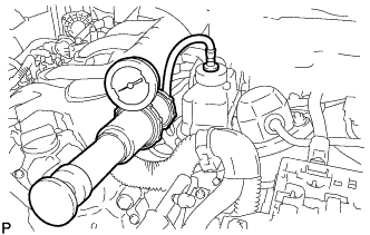
Install the radiator cap tester.
-
Pump the radiator cap tester to 137 kPa (1.4 kgf/ cm2, 20 psi), and then check that the pressure does not drop.
Tech Tips
If the pressure drops, check the hoses, radiator, water pump, inverter with converter, and hybrid vehicle transaxle assembly for leaks.
-
Reinstall the reservoir tank cap (for inverter).
-
-
INSTALL NO. 2 ENGINE UNDER COVER
-
Install the No. 2 engine under cover with the 4 screws and 2 grommets.
-
-
INSTALL FRONT SUSPENSION MEMBER BRACE
-
Install the front suspension member brace with the clip and 4 bolts.
- Torque:
- 52 N*m { 530 kgf*cm, 38 ft.*lbf }
-
-
INSTALL ENGINE UNDER COVER
-
Install the engine under cover with the 13 screws and 3 clips.
-