SUB RADIATOR INSTALLATION

-
INSTALL RADIATOR ASSEMBLY
-
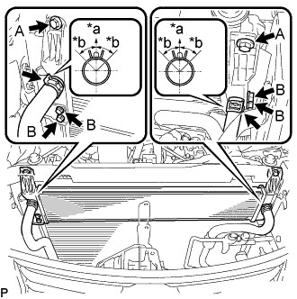
Text in Illustration *a Upper *b 30° Install the radiator with the 6 bolts.
- Torque:
- Bolt A
- 6.0 N*m { 61 kgf*cm, 53 in.*lbf }
- Bolt B
- 9.0 N*m { 92 kgf*cm, 80 in.*lbf }
-
Connect the 2 water hoses.
Note
-
Make sure that the clip is positioned as shown in the illustration.
-
Do not remove the tape or plastic bags from the pipes and disconnected hoses until installation.
-
-
-
INSTALL HOOD LOCK CONTROL CABLE COVER (w/ Cover)
-
Attach the guide to install the hood lock control cable cover.
-
-
INSTALL UPPER RADIATOR SUPPORT
-
Install the upper radiator support with the 5 bolts.
- Torque:
- 8.0 N*m { 82 kgf*cm, 71 in.*lbf }
-
Connect the 5 wire harness clamps and 3 connectors.
-
-
CONNECT HOOD LOCK CONTROL CABLE COVER (w/ Cover)
-
Attach the claw and install the 2 screws to connect the hood lock control cable cover.
-
-
CONNECT NO. 2 ENGINE ROOM WIRE
-
Connect the 6 wire harness clamps, connector and No. 2 engine room wire.
-
-
INSTALL HOOD LOCK ASSEMBLY (for RHD)
-
Connect the hood lock control cable to the hood lock.
-
Install the hood lock with the 3 bolts.
- Torque:
- 7.5 N*m { 76 kgf*cm, 66 in.*lbf }
-
-
INSTALL HOOD LOCK ASSEMBLY (for LHD)
-
Connect the hood lock control cable to the hood lock.
-
Install the hood lock with the 3 bolts.
- Torque:
- 7.5 N*m { 76 kgf*cm, 66 in.*lbf }
-
-
INSTALL HOOD LOCK RELEASE LEVER PROTECTOR
-
Install the hood lock release lever protector with the 2 clips.
-
Attach the 2 clamps and connect the connector.
-
-
INSTALL MILLIMETER WAVE RADAR SENSOR ASSEMBLY (w/ Dynamic Radar Cruise Control System)
-
ADD COOLANT (for Inverter)
Note
-
Do not reuse the drained coolant because it may contain foreign objects.
-
If the vehicle is driven with air in the inverter cooling system, damage may occur and the following DTCs may be set.
DTC Code Detection Item P0A04-725 Motor Electronics Coolant Temperature Sensor Circuit Intermittent P0A01-726 Motor Electronics Coolant Temperature Sensor Circuit Range / Performance P0A08-264 DC / DC Converter Status Circuit P0A78-284 Drive Motor "A" Inverter Performance P0A78-286 Drive Motor "A" Inverter Performance P0A7A-322 Generator Inverter Performance P0A7A-324 Generator Inverter Performance P0A93-346 Inverter Cooling System Performance P0A94-553 DC / DC Converter Performance P0A94-557 DC / DC Converter Performance P0AF1-276 Drive Motor Inverter Temperature Sensor "A" Circuit Intermittent / Erratic P0AEE-277 Motor Inverter Temperature Sensor "A" Circuit Range / Performance P0BD0-314 Generator Inverter Temperature Sensor Circuit Range / Erratic P0BCD-315 Generator Inverter Temperature Sensor Circuit Range / Performance P0C3C-625 DC / DC Converter Temperature Sensor "A" Intermittent / Erratic P0C39-626 DC / DC Converter Temperature Sensor "A" Range / Performance P0C41-627 DC / DC Converter Temperature Sensor "B" Intermittent / Erratic P0C3E-628 DC / DC Converter Temperature Sensor "B" Range / Performance P0C73-776 Motor Electronics Coolant Pump "A" Control Performance
-
Slowly pour coolant into the reservoir tank until it reaches the FULL line.
Standard Capacity Item Specified Condition for LHD 3.1 liters (3.3 US qts, 2.7 Imp. qts.) for RHD 2.9 liters (3.0 US qts, 2.6 Imp. qts.) Note
To prevent foreign matter such as dust or dirt from entering the cooling system, make sure to confirm that the container used to add coolant is clean and free of foreign matter such as dust or dirt.
-
When using the GTS:
-
Connect the GTS to the DLC3.
-
Turn the power switch on (IG).
-
Enter the following menus: Powertrain / Hybrid Control / Active Test / Activate the Water Pump.
-
Keep the coolant at the FULL line in the reservoir tank to compensate for the drop in coolant level when the air bleeds.
Standard Air bleeding from the inverter cooling system is completed when the noise made by the inverter water pump assembly becomes smaller and the circulation of coolant in the reservoir tank improves. Tech Tips
-
If free spinning of the inverter water pump is detected for approximately 5 seconds, failsafe control will be activated to suspend the operation of the pump for approximately 15 seconds and resume operation for approximately 4 seconds repeatedly. Operation of the inverter water pump will return to normal if coolant is added.
-
Loud noise made by the inverter water pump and poor circulation of coolant in the reservoir tank indicates that there is air in the cooling system.
-
-
-
When not using the GTS:
-
Turn the power switch on (READY).[*1]
-
Turn the power switch off and add coolant to the FULL line because the coolant level drops as the air bleeds.[*2]
Note
-
Be sure to turn the power switch off before adding SLLC.
-
Do not work on the components in the engine compartment while the vehicle is in the READY-on state because the engine is in intermittent operation.
-
-
Repeat steps [*1] and [*2] until air bleeding from the cooling system is completed.
Standard Air bleeding from the inverter cooling system is completed when the noise made by the inverter water pump assembly becomes smaller and the circulation of coolant in the reservoir tank improves. Tech Tips
Loud noise made by the inverter water pump and poor circulation of coolant in the reservoir tank indicates that there is air in the cooling system.
-
-
After the air is completely bled from the cooling system, tighten the reservoir tank cap.
-
Add coolant to the FULL line of the reservoir tank.
-
-
CONNECT CABLE TO AUXILIARY BATTERY NEGATIVE TERMINAL
Note
When disconnecting the cable, some systems need to be initialized after the cable is reconnected Click here.
-
INSPECT FOR COOLANT LEAK (for Inverter)
-
Remove the reservoir tank cap (for inverter).
CAUTION:
To avoid the danger of being burned, do not remove the reservoir tank cap while the coolant for the inverter is still hot.
-
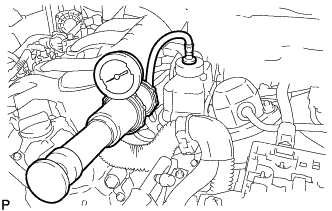
Install the radiator cap tester.
-
Pump the radiator cap tester to 137 kPa (1.4 kgf/ cm2, 20 psi), and then check that the pressure does not drop.
Tech Tips
If the pressure drops, check the hoses, radiator, water pump, inverter with converter, and hybrid vehicle transaxle assembly for leaks.
-
Reinstall the reservoir tank cap (for inverter).
-
-
INSTALL NO. 1 AIR CLEANER INLET
-
Install the No. 1 air cleaner inlet with the bolt.
- Torque:
- 5.0 N*m { 51 kgf*cm, 44 in.*lbf }
-
-
ADJUST MILLIMETER WAVE RADAR SENSOR ASSEMBLY (w/ Dynamic Radar Cruise Control System)
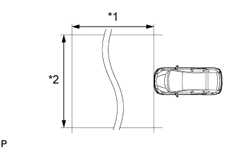
Text in Illustration *1 Approx. 10 m (32.8 ft.) *2 Approx. 14 m (45.9 ft.) Note
-
Perform measurements on a level surface.
-
Make sure that no large pieces of metal are within a 10 m (32.8 ft.) x 14 m (45.9 ft.) area in front of the vehicle. If possible, the surrounding area should also be free of large metal objects.
-
Before adjusting the radar beam axis, prepare the vehicle as follows.
-
Remove all excess weight from the vehicle (luggage, heavy objects, etc.).
-
Check the tire pressure and adjust it if necessary Click here.
-
-
Text in Illustration *1 Level Check and adjust the vertical direction of the radar sensor.
-
Remove dust, oil and foreign matter from the radar sensor's level rack.
-
Set a level on the radar sensor's level rack.
-
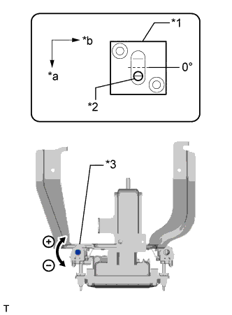
Text in Illustration *1 Level *2 Air Bubble *3 Bolt A *a FR *b LH Check that the level's air bubble is within the red frame.
OK Level's air bubble is within the red frame. If the bubble is not within the red frame, use a screwdriver to adjust bolt A until the air bubble is within the red frame.
Tech Tips
-
The adjustable range within the level's red frame is +/- 0.2°.
-
The target angle is +0.2° (upward angle of 0.2°).
Adjustment Adjustment Direction Adjustment Procedure Adjustment Angle Vertical adjustment Upward direction: Turn bolt A to negative (-) side For 1 complete turn of screwdriver, sensor moves about 0.12° Downward direction: Turn bolt A to positive (+) side
-
-
-
Text in Illustration *1 Millimeter Wave Radar Sensor Adjust the reflector height.
-
Adjust the reflector so that the center of SST reflector is the same height as the millimeter wave radar sensor.
- SST
- 09870-60000 ( 09870-60010 )
- 09870-60040
Tech Tips
Prepare a 10 m (32.8 ft.) string, a string with a sharp-pointed weight (plumb bob), and a 5 m (16.4 ft.) tape measure.
-
-
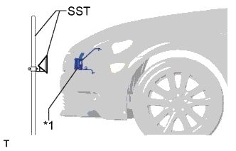
Place the reflector.
-
Hang the string (with weight) from the center of the vehicle's rear emblem. Mark the vehicle's rear center point on the ground. Repeat for the front of the vehicle.
-
Text in Illustration *a Adjust Center By Moving String To Right And Left *b Extend String Through Front Center Mark Set one end of the 10 m (32.8 ft.) string on the vehicle's rear center point. Run the string over the vehicle's front center point to a position 5 m (16.4 ft.) beyond the vehicle's front center point as shown in the illustration. Mark the 5 m (16.4 ft.) position.
-
Place the reflector (SST) at the marked position.
Note
Perform the operation as precisely as possible.
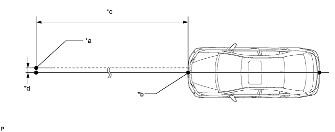
Text in Illustration *a Reflector (SST) Placement Point *b Millimeter Wave Radar Sensor Position *c 5 m (16.4 ft.) *d 13.1 mm (0.516 in.)
-
-
Check the radar beam axis.
-
When using the GTS:
-
Connect the GTS to the DLC3.
-
Turn the power switch on (IG).
-
Turn the GTS on, and turn the cruise control main switch on.
-
Select "Connect to Vehicle".
-
Select each item on the display screen and proceed to the next screen.
-
Under "System Selection Menu", select "Radar Cruise".
-
Select "Utility".
-
Select "Beam Axis Adjustment" and proceed to the next screen.
Tech Tips
A buzzer will sound for 1 second.
-
Follow the GTS display, and continue with the adjustment.
Note
-
Turn the cruise control main switch on before pressing "Next".
-
Make sure there is at least 20 cm (7.87 in.) between the radar sensor and any nearby individuals.
-
-
-
Check the following items on the radar cruise divergence data screen.
Note
While using the GTS beam axis adjustment mode, the actual direction and angle of the radar sensor may be different from the GTS data. In such a case, the deviation is displayed on the multi-information display in the combination meter.
-
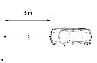
Confirm that the distance value is approximately 5 m (16.4 ft.).
Tech Tips
-
A value between 0.0 m (0.0 ft.) and 6.3 m (20.7 ft.) should be indicated.
-
If the distance is 0.0 m (0.0 ft.), the sensor cannot detect the target. Reconfirm that there is no metal in the specified area in front of the vehicle (refer to the Notice at the beginning of this adjustment procedure).
-
-
Confirm that the left/right side value is between 0.0 m (0.0 ft.) and 6.3 m (20.7 ft.).
Tech Tips
If the distance is 0.0 m (0.0 ft.), the sensor cannot detect the target. Reconfirm that there is no metal in the specified area in front of the vehicle (refer to the Notice at the beginning of this adjustment procedure).
-
-
-
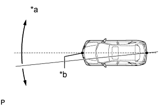
Check and adjust the horizontal direction of the radar sensor.
-
Check that the divergence of the radar beam axis is 0°.
Standard 0° (Both right and left) If the axis is not as specified, use a screwdriver to adjust bolt B until the divergence of the radar beam axis is 0°.
-
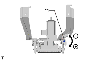
Text in Illustration *1 Bolt B Based on the measured divergence of the beam axis, turn and adjust bolt B for horizontal adjustment of the millimeter wave radar sensor using a screwdriver.
Adjustment Adjustment Direction Adjustment Procedure Adjustment Angle Horizontal adjustment Right direction: Turn bolt B to positive (+) side. For 1 complete turn of screwdriver, sensor moves about 0.07° Left direction: Turn bolt B to negative (-) side. Tech Tips
If the value does not change to 0°, it is possible that the sensor is aiming at something different. Reconfirm that there are no reflective materials in the surrounding area.
-
Finish the beam axis adjustment.
-
Disconnect the GTS from the DLC3.
-
-
Recheck and readjust the vertical direction of the radar sensor.
-
Text in Illustration *1 Level Set a level on the radar sensor's level rack.
-
Text in Illustration *1 Level *2 Air Bubble *3 Bolt A *a FR *b LH Check that the level's air bubble is within the red frame.
OK Level's air bubble is within the red frame. If the bubble is not within the red frame, use a screwdriver to adjust bolt A until the level's air bubble is within the red frame.
Tech Tips
-
The adjustable range within the red frame is +/- 0.2°.
-
The target angle is + 0.2° (upward angle of 0.2°).
Adjustment Adjustment Direction Adjustment Procedure Adjustment Angle Vertical adjustment Upward direction: Turn bolt A to negative (-) side For 1 complete turn of screwdriver, sensor moves about 0.12° Downward direction: Turn bolt A to positive (+) side
-
-
-
-
INSTALL COOL AIR INTAKE DUCT SEAL
-
Install the cool air intake duct seal with the 7 clips.
-
-
INSTALL ENGINE ROOM SIDE COVER
-
Install the engine room side cover with the 4 clips.
-
-
INSTALL NO. 2 ENGINE UNDER COVER
-
Install the No. 2 engine under cover with the 4 screws and 2 grommets.
-
-
INSTALL FRONT SUSPENSION MEMBER BRACE
-
Install the front suspension member brace with the clip and 4 bolts.
- Torque:
- 52 N*m { 530 kgf*cm, 38 ft.*lbf }
-
-
INSTALL ENGINE UNDER COVER
-
Install the engine under cover with the 13 screws and 3 clips.
-
-
INSTALL LUGGAGE COMPARTMENT TRIM COVER LH
-
Install the luggage compartment trim cover LH.
-
-
INSTALL LUGGAGE COMPARTMENT FLOOR MAT
-
Install the luggage compartment floor mat.
-