HYBRID CONTROL SYSTEM Brake Override System
DESCRIPTION
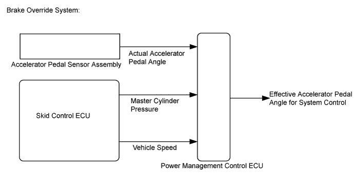
When the vehicle is being driven with the accelerator pedal depressed, depressing the brake pedal without releasing the accelerator pedal will activate the brake override system to restrict driving torque. The conditions for activating the brake override system as well as the items that are controlled are explained below.
-
Vehicle is being driven at or above a specified speed.
-
The accelerator pedal is depressed beyond a specified level, and then the brake pedal is depressed.
Note
Brake override control may not be performed depending on the relationship between accelerator pedal angle and vehicle speed.
-
Driving torque is restricted.
Tech Tips
During brake override system control, the value for the accelerator pedal angle (which is used for hybrid control) is forcibly reduced to a specified value. For this reason, the Data List value for Accelerator Degree will be replaced with a specified value regardless of the actual accelerator pedal angle (Accel Pedal Pos #1, Accel Pedal Pos #2).
Deactivation occurs when either of the following conditions is met:
-
The master cylinder pressure decreases below a specified value.
-
The actual accelerator pedal angle increases or decreases beyond the specified range.
INSPECTION PROCEDURE
Inspection MethodDrive at 10 km/h (6.25 mph), depress the accelerator pedal by 1/2 to 3/4 and keep it in that position. Under these conditions, if driving torque is controlled when the brake pedal is depressed by the left foot of the driver, it can be confirmed that the brake override system has operated.
CAUTION:
Perform this road test only in an appropriate safe location, in accordance with all local laws.
Pay careful attention to the surroundings when performing the road test.
Tech Tips
-
Under normal conditions, the Accelerator Degree value changes in response to the Accel Pedal Pos #1 value.
-
If the Data List values of Accelerator Degree and Accel Pedal Pos #1 do not match, and the value of Accel Pedal Pos #1 changes but the value of Accelerator Degree is constant, this confirms that the brake override system has operated. (Data can be captured relatively easily by using the snapshot function in Data List. Confirm the data after performing the road test.)
-
The brake override system restricts driving torque if the brake pedal is depressed when driving with the accelerator pedal depressed. If a customer reports experiencing a loss of power (driving torque) after the accelerator and brake pedals have both been intentionally depressed, explain that this is not a malfunction, and depressing both the accelerator and brake pedals at the same time should be avoided.
PROCEDURE
-
CHECK DTC OUTPUT (HEALTH CHECK)
-
Connect the GTS to the DLC3.
-
Turn the power switch on (IG).
-
Enter the following menus: System Select / Health Check.
-
Check DTCs.
Result Result Proceed to No DTCs are output. A DTCs are output. B -
Turn the power switch off.
B 
GO TO DTC CHART
A 
-
-
READ VALUE USING GTS (MASTER CYLINDER CTRL TRQ)
-
Connect the GTS to the DLC3.
-
Turn the power switch on (IG).
-
Enter the following menus: Powertrain / Hybrid Control / Data List / Master Cylinder Ctrl Trq.
-
Read the value displayed on the GTS.
Tester Display Measurement Item/Range Normal Condition Master Cylinder Ctrl Trq Master cylinder control torque/
Min.: -4096.0 Nm, Max.: 4095.0 Nm
Brake pedal depressed:
Changes with the brake pedal pressure
Result Result Proceed to Displayed value changes according to the brake pedal pressure. A Displayed speed value does not change according to the brake pedal pressure. B -
Turn the power switch off.
B
CHECK BRAKE ACTUATOR ASSEMBLY (ON-VEHICLE INSPECTION) Click here
A
-
-
READ VALUE USING GTS (ACCEL PEDAL POS #1, ACCEL PEDAL POS #2)
-
Connect the GTS to the DLC3.
-
Turn the power switch on (IG).
-
Enter the following menus: Powertrain / Hybrid Control / Data List / Accel Pedal Pos #1, Accel Pedal Pos #2.
-
Read the value displayed on the GTS.
Tester Display Measurement Item/Range Normal Condition Accel Pedal Pos #1 Accelerator pedal position sensor No.1/
Min.: 0.0%, Max.: 100.0%
Accelerator pedal depressed:
Changes with accelerator pedal pressure
Accel Pedal Pos #2 Accelerator pedal position sensor No.2/
Min.: 0.0%, Max.: 100.0%
Result Result Proceed to Displayed speed value smoothly changes following accelerator pedal operation. A Displayed speed value does not smoothly change following accelerator pedal operation. B -
Turn the power switch off.
B
REPLACE ACCELERATOR PEDAL SENSOR ASSEMBLY Click here
A
-
-
READ VALUE USING GTS (VEHICLE SPD)
-
Connect the GTS to the DLC3.
-
Turn the power switch on (READY).
-
Enter the following menus: Powertrain / Hybrid Control / Data List / Vehicle Spd.
-
Read the value displayed on the GTS.
Tester Display Measurement Item/Range Normal Condition Vehicle Spd Vehicle speed/
Min.: 0 km/h (0 mph), Max.: 255 km/h (158 mph)
Vehicle stopped:
0 km/h (0 mph)
While driving at a constant speed:
No significant fluctuation
Result Result Proceed to Displayed speed value does not fluctuate. A Displayed speed value fluctuates. B CAUTION:
Perform this road test only in an appropriate safe location, in accordance with all local laws.
Tech Tips
Data can be captured relatively easily by using the snapshot function in the Data List. Confirm the data after performing the drive test.
-
Turn the power switch off.
B
GO TO METER / GAUGE SYSTEM (HOW TO PROCEED WITH TROUBLESHOOTING) Click here
A
-
-
READ VALUE USING GTS (FR, FL, RR, RL WHEEL SPEED)
-
Connect the GTS to the DLC3.
-
Turn the power switch on (READY).
-
Enter the following menus: Chassis / ABS/VSC/TRAC / Data List / FR Wheel Speed, FL Wheel Speed, RR Wheel Speed and RL Wheel Speed.
-
Read the value displayed on the GTS.
Tester Display Measurement Item/Range Normal Condition FR Wheel Speed Front wheel speed sensor RH /
Min.: 0 km/h (0 mph), Max.: 326 km/h (202 mph)
Vehicle stopped:
0 km/h (0 mph)
When driving at constant speed:
No large fluctuations
FL Wheel Speed Front wheel speed sensor LH / /
Min.: 0 km/h (0 mph), Max.: 326 km/h (202 mph)
RR Wheel Speed Rear wheel speed sensor RH /
Min.: 0 km/h (0 mph), Max.: 326 km/h (202 mph)
RL Wheel Speed Rear wheel speed sensor LH /
Min.: 0 km/h (0 mph), Max.: 326 km/h (202 mph)
Result Result Proceed to Displayed speed value does not fluctuate. A Displayed speed value fluctuates. B CAUTION:
Perform this road test only in an appropriate safe location, in accordance with all local laws.
Tech Tips
Data can be captured relatively easily by using the snapshot function in the Data List. Confirm the data after performing the drive test.
-
Turn the power switch off.
B
GO TO ELECTRONICALLY CONTROLLED BRAKE SYSTEM (HOW TO PROCEED WITH TROUBLESHOOTING) Click here
A 
END
-