HYBRID CONTROL SYSTEM, Diagnostic DTC:P3110-223

| DTC Code | DTC Name |
|---|---|
| P3110-223 | HV Main Relay |
DESCRIPTION
The power management control ECU monitors the IGCT relay and detects the following malfunction.
| DTC No. | INF Code | DTC Detection Condition | Trouble Area |
|---|---|---|---|
| P3110 | 223 | There is a short to +B in the IGCT relay or the IGCT relay is stuck closed. |
|
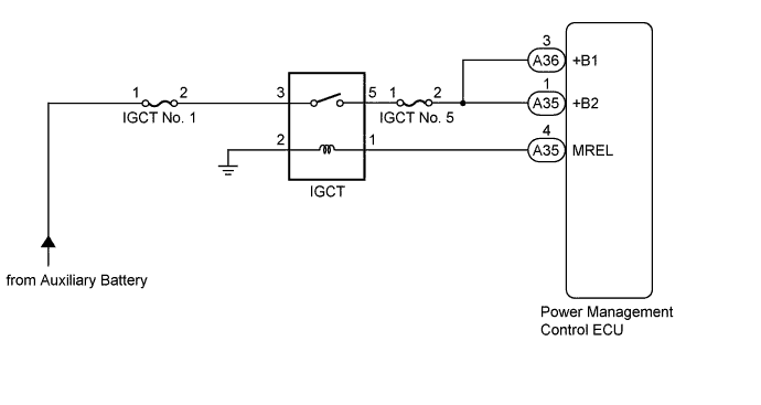
WIRING DIAGRAM
INSPECTION PROCEDURE
Tech Tips
If the auxiliary battery voltage is applied to terminal +B1 or +B2 of the power management control ECU, even though the power switch is off, the circuit is shorted to +B.
PROCEDURE
-
INSPECT RELAY (IGCT)
-
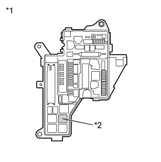
Text in Illustration *1 No. 1 Engine Room Relay Block and Junction Block Assembly *2 IGCT Relay Remove the IGCT relay from the No. 1 engine room relay block and junction block assembly.
-
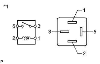
Text in Illustration *1 IGCT Relay Measure the resistance according to the value(s) in the table below.
Standard Resistance Tester Connection Condition Specified Condition 3 - 5 Auxiliary battery voltage is not applied between terminals 1 and 2 10 kΩ or higher -
Install the IGCT relay.
NG 
REPLACE RELAY (IGCT)
OK 
-
-
CHECK HARNESS AND CONNECTOR (POWER MANAGEMENT CONTROL ECU - NO. 1 ENGINE ROOM RELAY BLOCK AND JUNCTION BLOCK ASSEMBLY)
-
Remove the IGCT relay from the No. 1 engine room relay block and junction block assembly.
-
Disconnect the connector from the power management control ECU.
-
Measure the voltage according to the value(s) in the table below.
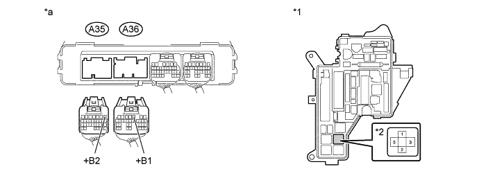
Text in Illustration *1 No. 1 Engine Room Relay Block and Junction Block Assembly *2 IGCT relay *a Rear view of wire harness connector
(to Power Management Control ECU)
- - Standard Voltage Tester Connection Switch Condition Specified Condition A36-3 (+B1), A35-1 (+B2) or 5 (IGCT relay) - Body ground Power switch off Below 1 V -
Install the IGCT relay.
-
Connect the power management control ECU connector.
NG
REPAIR OR REPLACE HARNESS OR CONNECTOR
OK 
REPLACE POWER MANAGEMENT CONTROL ECU Click here
-