HYBRID CONTROL SYSTEM, Diagnostic DTC:P0867-882, P0989-899

| DTC Code | DTC Name |
|---|---|
| P0867-882 | Transmission Fluid Pressure |
| P0989-899 | Transmission Fluid Pressure Sensor / Switch "E" Circuit Low |
DESCRIPTION
Refer to the description for DTC P0731-871 Click here.
| DTC No. | INF Code | DTC Detection Condition | Trouble Area |
|---|---|---|---|
| P0867 | 882 |
|
|
| P0989 | 899 | If P0867 is stored, P0989-899 (oil pressure switch (PB3) malfunction (low)) is detected. (If P0867-882 is stored due to a low line pressure malfunction, P0989-899 will not be detected.) (2 trip detection logic) |
Tech Tips
The ST-on state is a state that occurs when the READY indicator in the combination meter blinks after the power switch is pressed with the brake pedal depressed.
INSPECTION PROCEDURE
PROCEDURE
-
CHECK DTC OUTPUT (HYBRID CONTROL)
-
Connect the GTS to the DLC3.
-
Turn the power switch on (IG).
-
Enter the following menus: Powertrain / Hybrid Control / Trouble Codes.
-
Check if DTCs are output.
Result Result Proceed to P0867-882 or P0989-899 only is output. A Any of the following DTCs are also output. B DTC No. Relevant Diagnosis P2720-852 Pressure Control Solenoid Circuit Low Voltage P2721-853 Pressure Control Solenoid Circuit High Voltage P2797-881 Auxiliary Transmission Fluid Pump Control Performance P0C29-865 Auxiliary Transmission Fluid Pump Driver Circuit Performance P0C2C-888, 889 Auxiliary Transmission Fluid Pump Control Module Feedback Signal Range / Performance P0C2D-858 Auxiliary Transmission Fluid Pump Control Module Feedback Signal Low P0C2E-859 Auxiliary Transmission Fluid Pump Control Module Feedback Signal High -
Turn the power switch off.
B 
GO TO DTC CHART (HYBRID CONTROL SYSTEM) Click here
A 
-
-
CHECK CONNECTOR CONNECTION CONDITION (POWER MANAGEMENT CONTROL ECU CONNECTOR)
-
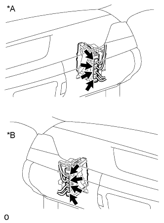
Text in Illustration *A for LHD *B for RHD Check the connector connections and contact pressure of the relevant terminals for the power management control ECU connectors Click here.
OK The connectors are connected securely and there are no contact pressure problems.
NG
CONNECT SECURELY
OK
-
-
CHECK CONNECTOR CONNECTION CONDITION (TRANSMISSION WIRE CONNECTOR)
-
Check the connection of the transmission wire connector Click here.
OK The connector is connected securely and there are no contact problems.
NG
CONNECT SECURELY
OK
-
-
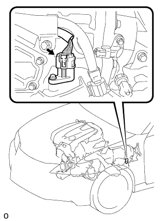
CHECK CONNECTOR CONNECTION CONDITION (OIL PUMP MOTOR CONTROLLER CONNECTOR)
Note
Before disconnecting the connectors, confirm that they are properly connected by checking that the locking claws are engaged and that the connectors cannot be pulled out.
-
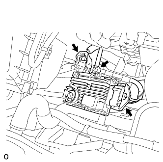
Check the connections of the oil pump motor controller connectors Click here.
OK The connectors are connected securely and there are no contact problems. Tech Tips
For connector A, when connecting it, insert it with the locking lever in the raised position. Rotate the lever downward and make sure that the connector is pulled into its socket. When the locking lever is in its fully closed position, a click will be heard as its locking claws engage. After the click is heard, pull up on the connector to confirm that it is properly connected.
NG
CONNECT SECURELY
OK
-
-
CHECK FUSIBLE LINK (OIL PMP)
-
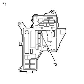
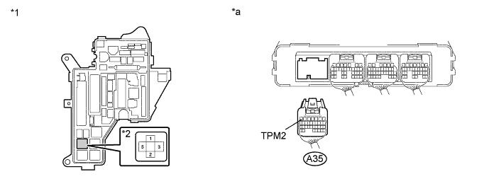
Text in Illustration *1 No. 1 Engine Room Relay Block and Junction Block Assembly *2 Fusible Link (OIL PMP) Check if there is an open circuit in the fusible link (OIL PMP) in the No. 1 engine room relay block and junction block assembly.
OK There is no open circuit in the fusible link (OIL PMP).
NG
REPLACE FUSIBLE LINK (OIL PMP)
OK
-
-
CHECK HYBRID VEHICLE TRANSMISSION ASSEMBLY (SOLENOID VALVE (SP), OIL PRESSURE SWITCH (PB3))
-
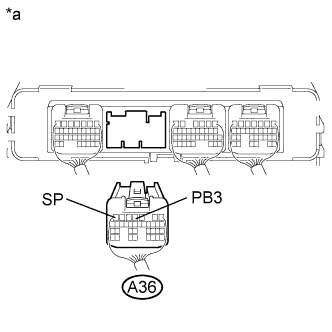
Text in Illustration *a Rear view of wire harness connector
(to Power Management Control ECU)
Disconnect the connector from the power management control ECU.
-
Measure the resistance according to the value(s) in the table below.
Standard Resistance Tester Connection Condition Specified Condition A36-7 (SP) - Body ground 68°F (20°C) 11 to 15 Ω Standard Resistance Tester Connection Switch Condition Specified Condition A36-4 (PB3) - Body ground Power switch off 10 kΩ or higher Result Result Proceed to Normal A Oil pressure switch (PB3) result is not as specified B Solenoid valve (SP) result is not as specified C -
Connect the power management control ECU connector.
B 
CHECK HARNESS AND CONNECTOR (POWER MANAGEMENT CONTROL ECU - TRANSMISSION WIRE) Click here
C
A
-
-
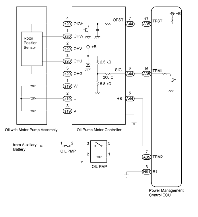
CHECK HARNESS AND CONNECTOR (POWER MANAGEMENT CONTROL ECU - OIL PUMP MOTOR CONTROLLER)
-
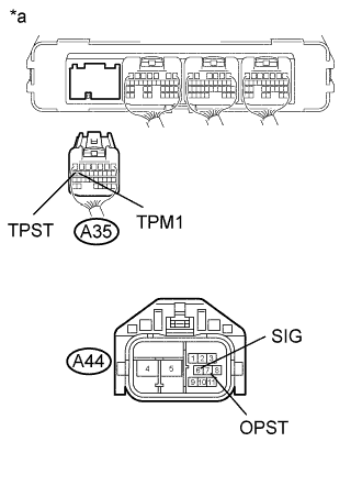
Text in Illustration *a Rear view of wire harness connector
(to Power Management Control ECU)
*b Front view of wire harness connector
(to Oil Pump Motor Controller)
Disconnect the connector from the power management control ECU.
-
Disconnect the connector from the oil pump motor controller.
-
Turn the power switch on (IG).
-
Measure the voltage according to the value(s) in the table below.
Standard Voltage Tester Connection Switch Condition Specified Condition A35-16 (TPM1) - Body ground Power switch on (IG) Below 1 V A35-17 (TPST) - Body ground Power switch on (IG) Below 1 V Note
Turning the power switch on (IG) with the power management control ECU and oil pump motor controller connectors disconnected causes other DTCs to be stored. Clear the DTCs after performing this inspection.
-
Turn the power switch off.
-
Measure the resistance according to the value(s) in the table below.
Standard Resistance Tester Connection Switch Condition Specified Condition A35-16 (TPM1) - A44-6 (SIG) Power switch off Below 1 Ω A35-17 (TPST) - A44-7 (OPST) Power switch off Below 1 Ω A35-16 (TPM1) - Body ground and other terminals Power switch off 10 kΩ or higher A35-17 (TPST) - Body ground and other terminals Power switch off 10 kΩ or higher -
Connect the power management control ECU connector.
-
Connect the oil pump motor controller connector.
NG
REPAIR OR REPLACE HARNESS OR CONNECTOR
OK
-
-
CHECK RELAY (OIL PMP)
-
Text in Illustration *1 No. 1 Engine Room Relay Block and Junction Block Assembly *2 OIL PMP Relay Remove the OIL PMP relay from the No. 1 engine room relay block and junction block assembly.
-
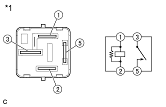
Text in Illustration *1 OIL PMP Relay Measure the resistance according to the value(s) in the table below.
Standard Resistance Tester Connection Condition Specified Condition 1 - 2 Always 151 to 203 Ω 3 - 5 Auxiliary battery voltage is not applied between terminals 1 and 2 10 kΩ or higher Auxiliary battery voltage is applied between terminals 1 and 2 Below 1 Ω -
Install the OIL PMP relay to the No. 1 engine room relay block and junction block assembly.
NG
REPLACE RELAY (OIL PMP)
OK
-
-
CHECK OIL WITH MOTOR PUMP ASSEMBLY
-
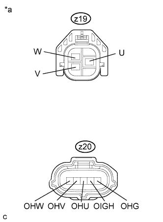
Text in Illustration *a Front view of wire harness connector
(to Oil Pump Motor Controller)
Disconnect the connectors from the oil pump motor controller.
-
Turn the power switch on (IG).
-
Measure the voltage according to the value(s) in the table below.
Standard Voltage Tester Connection Switch Condition Specified Condition Z19-1 (W) - Body ground Power switch on (IG) Below 1 V Z19-2 (U) - Body ground Power switch on (IG) Below 1 V Z19-3 (V) - Body ground Power switch on (IG) Below 1 V z20-1 (OHW) - Body ground Power switch on (IG) Below 1 V z20-2 (OHV) - Body ground Power switch on (IG) Below 1 V z20-3 (OHU) - Body ground Power switch on (IG) Below 1 V z20-4 (OIGH) - Body ground Power switch on (IG) Below 1 V z20-5 (OHG) - Body ground Power switch on (IG) Below 1 V Note
Turning the power switch on (IG) with the oil pump motor controller connectors disconnected causes other DTCs to be stored. Clear the DTCs after performing this inspection.
-
Turn the power switch off.
-
Measure the resistance according to the value(s) in the table below.
Standard Resistance Tester Connection Switch Condition Specified Condition z19-1 (W) - z19-2 (U) Power switch off Below 1 Ω z19-1 (W) - z19-3 (V) Power switch off Below 1 Ω z19-1 (W) - Body ground Power switch off 10 kΩ or higher z19-2 (U) - Body ground Power switch off 10 kΩ or higher z19-3 (V) - Body ground Power switch off 10 kΩ or higher z20-1 (OHW) - Body ground Power switch off 10 kΩ or higher z20-2 (OHV) - Body ground Power switch off 10 kΩ or higher z20-3 (OHU) - Body ground Power switch off 10 kΩ or higher z20-4 (OIGH) - Body ground Power switch off 10 kΩ or higher z20-5 (OHG) - Body ground Power switch off 10 kΩ or higher -
Connect the oil pump motor controller connector.
NG
REPLACE OIL WITH MOTOR PUMP ASSEMBLY Click here
OK
-
-
CHECK OIL PUMP MOTOR CONTROLLER (POWER SOURCE CIRCUIT)
-
Disconnect the connector from the oil pump motor controller.
-
Turn the power switch on (IG).
-
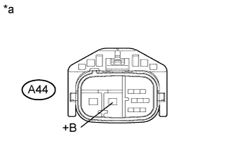
Text in Illustration *a Front view of wire harness connector
(to Oil Pump Motor Controller)
Measure the voltage according to the value(s) in the table below.
Standard Voltage Tester Connection Switch Condition Specified Condition A44-5 (+B) - Body ground Power switch on (IG) 11 to 14 V -
Turn the power switch off.
-
Text in Illustration *1 No. 1 Engine Room Relay Block and Junction Block Assembly *2 OIL PMP Relay Remove the OIL PMP relay from the No. 1 engine room relay block and junction block assembly.
-
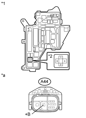
Text in Illustration *1 No. 1 Engine Room Relay Block and Junction Block Assembly *2 OIL PMP Relay *a Front view of wire harness connector
(to Oil Pump Motor Controller)
Measure the resistance according to the value(s) in the table below.
Standard Resistance Tester Connection Switch Condition Specified Condition 5 (OIL PMP relay) - A44-5 (+B) Power switch off Below 1 Ω 2 (OIL PMP relay) - Body ground Power switch off Below 1 Ω 5 (OIL PMP relay) - Body ground Power switch off 10 kΩ or higher -
Disconnect the connector from the power management control ECU.
Text in Illustration *1 No. 1 Engine Room Relay Block and Junction Block Assembly *2 OIL PMP Relay *a Rear view of wire harness connector
(to Power Management Control ECU)
- - -
Turn the power switch off.
-
Measure the resistance according to the value(s) in the table below.
Standard Resistance Tester Connection Switch Condition Specified Condition 1 (OIL PMP relay) - A35-7 (TPM2) Power switch off Below 1 Ω 1 (OIL PMP relay) or A35-7 (TPM2) - Body ground Power switch off 10 kΩ or higher -
Connect the oil pump motor controller connector.
-
Install the OIL PMP relay to the No. 1 engine room relay block and junction block assembly.
-
Connect the power management control ECU connector.
NG
REPAIR OR REPLACE HARNESS OR CONNECTOR
OK
-
-
READ VALUE USING GTS (LINE PRESSURE)
-
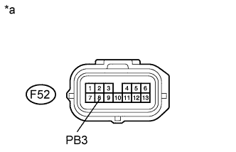
Text in Illustration *a Front view of wire harness connector
(to Transmission Wire)
Disconnect the transmission wire connector.
-
Connect the GTS to the DLC3.
-
Turn the power switch on (IG).
Note
Turning the power switch on (IG) with the transmission wire connector disconnected causes other DTCs to be stored. Clear the DTCs after performing this inspection.
-
Enter the following menus: Powertrain / Hybrid Control / Data List / Line Pressure.
-
Read the Data List.
OK Tester Display Condition Specified Condition Line Pressure F52-8 (PB3) is connected to body ground ON F52-8 (PB3) is not connected to body ground OFF -
Turn the power switch off.
-
Connect the transmission wire connector.
NG
CHECK HARNESS AND CONNECTOR (POWER MANAGEMENT CONTROL ECU - TRANSMISSION WIRE) Click here
OK
-
-
CLEAR DTC
-
Connect the GTS to the DLC3.
-
Turn the power switch on (IG).
-
Enter the following menus: Powertrain / Hybrid Control / Trouble Codes.
-
Read and record the DTCs and freeze frame data.
-
Clear DTCs and freeze frame data.
-
Turn the power switch off.
NEXT
-
-
READ VALUE USING GTS (LINE PRESSURE SOLENOID, B2 OIL PRESSURE SENSOR, LINE PRESSURE)
-
Connect the GTS to the DLC3.
-
Turn the power switch on (IG).
-
Enter the following menus: Powertrain / Hybrid Control / Data List / Line Pressure Solenoid, B2 Oil Pressure Sensor, Line Pressure.
-
Check the Data List items for approximately 8 seconds after pressing the power switch with the brake pedal depressed.
Line Pressure Solenoid B2 Oil Pressure Sensor Line Pressure Malfunction Condition OFF ON OFF Oil pressure switch (PB3) malfunction OFF OFF OFF Hybrid vehicle transmission assembly malfunction Result Result Proceed Result is not as specified (READY indicator comes on within 8 seconds after pressing the power switch) A Oil pressure switch (PB3) malfunction B Hybrid vehicle transmission assembly malfunction C -
Turn the power switch off.
B
CHECK CONNECTOR CONNECTION CONDITION (OIL PRESSURE SWITCH (PB3)) Click here
C
REPLACE HYBRID VEHICLE TRANSMISSION ASSEMBLY Click here
A
-
-
SIMULATION TEST
-
Connect the GTS to the DLC3.
-
Turn the power switch on (IG).
-
Enter the following menus: Powertrain / Hybrid Control / Active Test / Activate the Oil Pump (500rpm), Activate the Oil Pump (1000rpm).
-
Select OPM Revolution in the Data List.
-
Perform the "Activate the Oil Pump (500rpm)" and "Activate the Oil Pump (1000rpm)" Active Tests.
OK For both the "Activate the Oil Pump (500rpm)" and "Activate the Oil Pump (1000rpm)" Active Tests, the value of "OPM Revolution" is almost the same as the corresponding Active Test speed. Note
Make sure that the auxiliary battery is not discharged.
-
Turn the power switch off.
NG
REPLACE OIL WITH MOTOR PUMP ASSEMBLY Click here
OK
-
-
SIMULATION TEST
-
Connect the GTS to the DLC3.
-
Turn the power switch on (IG).
-
Enter the following menus: Powertrain / Hybrid Control / Data List / Line Pressure, Line Pressure Solenoid.
-
Turn the power switch on (READY).
-
10 seconds later, read the Data List.
OK "Line Pressure" remains OFF when "Line Pressure Solenoid" is ON. -
Enter the following menus: Powertrain / Hybrid Control / Trouble Codes.
-
Check if DTCs are output.
OK DTCs are not output. -
Enter the following menus: Powertrain / Hybrid Control / Active Test / Control the Shift Position.
-
Select B1 Oil Pressure, B2 Oil Pressure Sensor, Line Pressure and Line Pressure Solenoid in the Data List.
-
Perform the "Control the Shift Position" Active Test.
-
Switch the shift position between "Lo" and "Hi" several times using the "Control the Shift Position" Active Test.
OK Item Condition Specified Condition Data List B1 Oil Pressure B2 Oil Pressure Sensor Line Pressure Line Pressure Solenoid Control the Shift Position Lo OFF ON ON OFF Hi ON OFF ON OFF Note
Transmission system DTCs may be stored if the "Control the Shift Position" Active Test is canceled before it is completed.
-
Turn the power switch off.
NG
REPLACE HYBRID VEHICLE TRANSMISSION ASSEMBLY Click here
OK
-
-
CHECK FOR INTERMITTENT PROBLEMS
NG
REPAIR OR REPLACE MALFUNCTIONING PARTS, COMPONENT AND AREA
OK
-
CHECK FLUID LEAKS
-
Check for fluid leaks from the hybrid vehicle transmission assembly.
OK There are no fluid leaks.
NG
REPAIR OR REPLACE HYBRID VEHICLE TRANSMISSION ASSEMBLY Click here
OK
-
-
CHECK CONNECTOR CONNECTION CONDITION (OIL PRESSURE SWITCH (PB3))
-
Remove the oil strainer assembly Click here.
-
Check the connection of the oil pressure switch (PB3) connector Click here.
OK The connector is connected securely and there are no contact problems. -
Install the oil strainer assembly.
NG
CONNECT SECURELY
OK
-
-
CHECK TRANSMISSION WIRE
-
Remove the oil strainer assembly Click here.
-
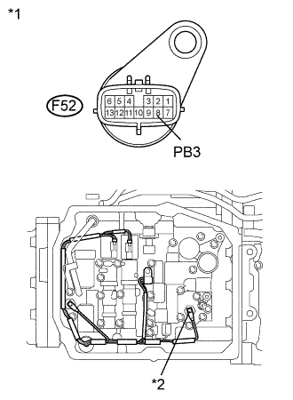
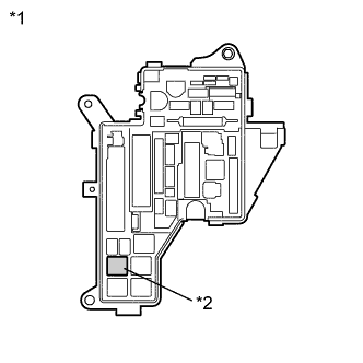
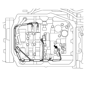
Text in Illustration *1 Transmission Wire *2 Oil Pressure Switch (PB3) Disconnect the transmission wire connector.
-
Disconnect the connector from the oil pressure switch (PB3).
-
Turn the power switch on (IG).
-
Measure the voltage according to the value(s) in the table below.
Standard Voltage Tester Connection Switch Condition Specified Condition F52-8 (PB3) - Body ground Power switch on (IG) Below 1 V Note
Turning the power switch on (IG) with the transmission wire connector disconnected causes other DTCs to be stored. Clear the DTCs after performing this inspection.
-
Turn the power switch off.
-
Measure the resistance according to the value(s) in the table below.
Standard Resistance Tester Connection Switch Condition Specified Condition F52-8 (PB3) - Transmission wire oil pressure switch (PB3) side Power switch off Below 1 Ω F52-8 (PB3) or Transmission wire oil pressure switch (PB3) side - Body ground and other terminals Power switch off 10 kΩ or higher -
Connect the transmission wire connector.
-
Connect the connector to the oil pressure switch (PB3).
-
Install the oil strainer assembly.
NG
REPLACE TRANSMISSION WIRE Click here
OK 
REPLACE OIL PRESSURE SWITCH (PB3) Click here
-
-
CHECK HARNESS AND CONNECTOR (POWER MANAGEMENT CONTROL ECU - TRANSMISSION WIRE)
-
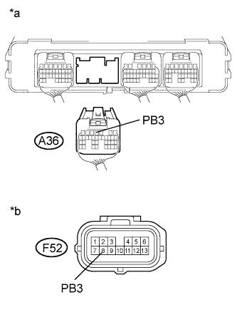
Text in Illustration *a Rear view of wire harness connector
(to Power Management Control ECU)
*b Front view of wire harness connector
(to Transmission Wire)
Disconnect the power management control ECU connector.
-
Disconnect the transmission wire connector.
-
Turn the power switch on (IG).
-
Measure the voltage according to the value(s) in the table below.
Standard Voltage Tester Connection Switch Condition Specified Condition A36-4 (PB3) - Body ground Power switch on (IG) Below 1 V Note
Turning the power switch on (IG) with the power management control ECU connector disconnected causes other DTCs to be stored. Clear the DTCs after performing this inspection.
-
Turn the power switch off.
-
Measure the resistance according to the value(s) in the table below.
Standard Resistance Tester Connection Switch Condition Specified Condition A36-4 (PB3) - F52-8 (PB3) Power switch off Below 1 Ω A36-4 (PB3) or F52-8 (PB3) - Body ground and other terminals Power switch off 10 kΩ or higher -
Connect the power management control ECU connector.
-
Connect the transmission wire connector.
NG
REPAIR OR REPLACE HARNESS OR CONNECTOR
OK
-
-
CHECK CONNECTOR CONNECTION CONDITION (OIL PRESSURE SWITCH (PB3))
-
Remove the oil strainer assembly Click here.
-
Check the connection of the oil pressure switch (PB3) connector Click here.
OK The connector is connected securely and there are no contact problems. -
Install the oil strainer assembly.
NG
CONNECT SECURELY
OK
-
-
CHECK TRANSMISSION WIRE
-
Remove the oil strainer assembly Click here.
-
Text in Illustration *a Transmission Wire *b Oil Pressure Switch (PB3) Disconnect the transmission wire connector.
-
Disconnect the connector from the oil pressure switch (PB3).
-
Turn the power switch on (IG).
-
Measure the voltage according to the value(s) in the table below.
Standard Voltage Tester Connection Switch Condition Specified Condition F52-8 (PB3) - Body ground Power switch on (IG) Below 1 V Note
Turning the power switch on (IG) with the transmission wire connector disconnected causes other DTCs to be stored. Clear the DTCs after performing this inspection.
-
Turn the power switch off.
-
Measure the resistance according to the value(s) in the table below.
Standard Resistance Tester Connection Switch Condition Specified Condition F52-8 (PB3) - Transmission wire oil pressure switch (PB3) side Power switch off Below 1 Ω F52-8 (PB3) or Transmission wire oil pressure switch (PB3) side - Body ground and other terminals Power switch off 10 kΩ or higher -
Connect the transmission wire connector.
-
Connect the connector to the oil pressure switch (PB3).
-
Install the oil strainer assembly.
NG
REPLACE TRANSMISSION WIRE Click here
OK
REPLACE OIL PRESSURE SWITCH (PB3) Click here
-
-
CHECK HARNESS AND CONNECTOR (POWER MANAGEMENT CONTROL ECU - TRANSMISSION WIRE)
-
Text in Illustration *a Rear view of wire harness connector
(to Power Management Control ECU)
*b Front view of wire harness connector
(to Transmission Wire)
Disconnect the power management control ECU connector.
-
Disconnect the transmission wire connector.
-
Turn the power switch on (IG).
-
Measure the voltage according to the value(s) in the table below.
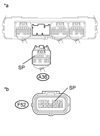
Standard Voltage Tester Connection Switch Condition Specified Condition A36-7 (SP) - Body ground Power switch on (IG) Below 1 V Note
Turning the power switch on (IG) with the power management control ECU connector disconnected causes other DTCs to be stored. Clear the DTCs after performing this inspection.
-
Turn the power switch off.
-
Measure the resistance according to the value(s) in the table below.
Standard Resistance Tester Connection Switch Condition Specified Condition A36-7 (SP) - F52-4 (SP) Power switch off Below 1 Ω A36-7 (SP) or F52-4 (SP) - Body ground and other terminals Power switch off 10 kΩ or higher Tech Tips
The solenoid valve (SP) is not available separately. If it requires replacement, replace the hybrid vehicle transmission assembly
-
Connect the power management control ECU connector.
-
Connect the transmission wire connector.
NG
REPAIR OR REPLACE HARNESS OR CONNECTOR
OK
REPLACE HYBRID VEHICLE TRANSMISSION ASSEMBLY Click here
-
-
CHECK HARNESS AND CONNECTOR (POWER MANAGEMENT CONTROL ECU - TRANSMISSION WIRE)
-
Text in Illustration *a Rear view of wire harness connector
(to Power Management Control ECU)
*b Front view of wire harness connector
(to Transmission Wire)
Disconnect the power management control ECU connector.
-
Disconnect the transmission wire connector.
-
Turn the power switch on (IG).
-
Measure the voltage according to the value(s) in the table below.
Standard Voltage Tester Connection Switch Condition Specified Condition A36-4 (PB3) - Body ground Power switch on (IG) Below 1 V Note
Turning the power switch on (IG) with the power management control ECU connector disconnected causes other DTCs to be stored. Clear the DTCs after performing this inspection.
-
Turn the power switch off.
-
Measure the resistance according to the value(s) in the table below.
Standard Resistance Tester Connection Switch Condition Specified Condition A36-4 (PB3) - F52-8 (PB3) Power switch off Below 1 Ω A36-4 (PB3) or F52-8 (PB3) - Body ground and other terminals Power switch off 10 kΩ or higher -
Connect the power management control ECU connector.
-
Connect the transmission wire connector.
NG
REPAIR OR REPLACE HARNESS OR CONNECTOR
OK
REPLACE POWER MANAGEMENT CONTROL ECU Click here
-
-
CHECK CONNECTOR CONNECTION CONDITION (OIL PRESSURE SWITCH (PB3))
-
Remove the oil strainer assembly Click here.
-
Check the connection of the oil pressure switch (PB3) connector Click here.
OK The connector is connected securely and there are no contact problems. -
Install the oil strainer assembly.
NG
CONNECT SECURELY
OK
-
-
CHECK TRANSMISSION WIRE
-
Remove the oil strainer assembly Click here.
-
Text in Illustration *1 Transmission Wire *2 Oil Pressure Switch (PB3) Disconnect the transmission wire connector.
-
Disconnect the connector from the oil pressure switch (PB3).
-
Turn the power switch on (IG).
-
Measure the voltage according to the value(s) in the table below.
Standard Voltage Tester Connection Switch Condition Specified Condition F52-8 (PB3) - Body ground Power switch on (IG) Below 1 V Note
Turning the power switch on (IG) with the transmission wire connector disconnected causes other DTCs to be stored. Clear the DTCs after performing this inspection.
-
Turn the power switch off.
-
Measure the resistance according to the value(s) in the table below.
Standard Resistance Tester Connection Switch Condition Specified Condition F52-8 (PB3) - Transmission wire oil pressure switch (PB3) side Power switch off Below 1 Ω F52-8 (PB3) or Transmission wire oil pressure switch (PB3) side - Body ground and other terminals Power switch off 10 kΩ or higher -
Connect the transmission wire connector.
-
Connect the connector to the oil pressure switch (PB3).
-
Install the oil strainer assembly.
NG
REPLACE TRANSMISSION WIRE Click here
OK
REPLACE OIL PRESSURE SWITCH (PB3) Click here
-